- Key takeaways
- Part 1. Define the robot vacuum battery bay and pack envelope
- Part 2. Compare pouch and cylindrical robot vacuum battery packs
- Part 3. Design the robot vacuum battery connector and harness
- Part 4. Validate the low-profile robot vacuum battery pack in the chassis
- Part 5. Low-profile robot vacuum battery pack design FAQs
Start with the smallest assembled battery bay and the usable energy needed to finish a cleaning route. Use those limits to compare complete battery packs, including the protection board, harness, and connector.
Key takeaways
- Allow for cover movement and fitting clearance when setting the maximum pack height.
- Compare pouch and cylindrical layouts in the same bay against the same energy and peak-load requirements.
- Check harness routing with the cover closed and connector access through the service opening.
Part 1. Define the robot vacuum battery bay and pack envelope
Start with a cross-section of the assembled battery bay. Measure from the surface that supports the pack to the closest obstruction above it. Check cover ribs, screw bosses, and nearby parts. The tightest point may sit over the protection board or wire exit.
Mark two areas on the drawing:
- Installed space covers the pack, its mounting features, the mated connector, and the routed wires with the cover closed.
- Service space covers the movement needed to release the connector and lift or slide the pack out.
Set the energy target before comparing cell layouts. If the project starts with a runtime goal, size the battery for hard floors and carpet to convert that goal into usable watt-hours (Wh). Give the supplier the minimum loaded pack voltage and the peak discharge current, duration, and repetition rate during carpet boost.
Part 2. Compare pouch and cylindrical robot vacuum battery packs
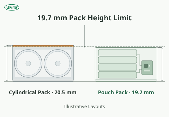
Compare the maximum dimensions of each finished pack. A cylindrical layout includes cell holders, insulation, and wrap. A pouch layout includes the cell stack, tabs, protection board, and padding. Confirm with the supplier how the pouch design accounts for changes in thickness during use.
Worked example for a 21 mm battery bay
These dimensions are illustrative. Both layouts have the same 51 Wh usable-energy target and the same carpet-boost load requirement.
| Height budget | Example value |
|---|---|
| Smallest assembled bay height | 21.0 mm |
| Allowance for inward cover movement | −0.6 mm |
| Fitting clearance | −0.7 mm |
| Maximum in-service pack height | 19.7 mm |
The 21.0 mm figure already includes the chassis and cover manufacturing tolerances. The 0.6 mm allowance covers additional inward movement in use. Keep these two items separate in the calculation.
| Candidate layout | Finished height check | Design decision |
|---|---|---|
| Cylindrical cells laid flat | 18.6 mm cell diameter + 1.4 mm total for the holder + 0.5 mm total for insulation and wrap = 20.5 mm | Exceeds the height limit by 0.8 mm. Revise the holder or bay geometry before sampling. |
| Pouch pack with the board beside the cells | 19.2 mm maximum in service, including the agreed allowance for thickness change | Leaves 0.5 mm within the height budget. Check the board and wire exit against the available length and width. |
The cylindrical calculation uses the maximum diameter from Molicel’s INR-18650-P28A cell dimensions. The holder, insulation, and pouch dimensions are example design values.
Ask the supplier to mark the highest points around the protection board, wire exit, and connector on the finished pack drawing. Then verify that the proposed layout can deliver the required 51 Wh and maintain the minimum pack voltage during carpet boost.
Part 3. Design the robot vacuum battery connector and harness
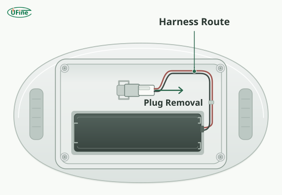
Show the harness in its installed position on the assembly drawing. Include the connector in both its fully seated position and its removal position. This gives the mechanical and electrical teams a common reference for fit and service access.
| Drawing detail | What to specify |
|---|---|
| Wire exit | The exit location and direction, the route to the socket, and the areas the leads must clear |
| Connector access | Plug and socket part numbers, latch location, unplugging direction, and hand or tool clearance |
| Harness length | The measurement points, length tolerance, and space for slack with the longest allowed harness |
| Removal path | The direction the disconnected pack moves and any parts that must be removed first |
Define the connector pinout, polarity, and any temperature or pack identification signals. If the robot reads a thermistor, specify its resistance curve and its position in the pack. Identify where charge control sits in the system. Texas Instruments’ robot vacuum charging design guide illustrates how the dock, charging circuit, and battery pack can work together.
Part 4. Validate the low-profile robot vacuum battery pack in the chassis
Use a representative chassis with the intended cover, harness, controller, and charging dock. Agree on the pass criteria before testing.
| Validation check | What a passing sample should do |
|---|---|
| Closed-cover fit | Let the cover seat correctly while maintaining the specified clearance at the pack’s highest points. |
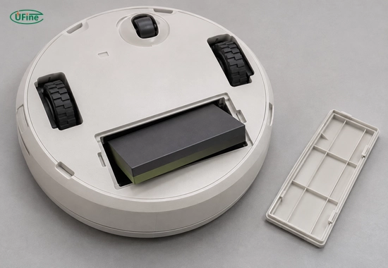
| Service removal | Let a technician release the plug and remove the pack through the intended opening without pulling on the wires. After reassembly, the harness should show no pinch marks. |
| Carpet boost at low charge | Keep the pack and controller input above their agreed voltage limits throughout the current peak. The robot should enter boost without a reset or unintended cutoff. |
| Mixed-floor cleaning route | Deliver the required usable Wh, finish the target route, and retain enough energy to reach the dock. |
| Dock charging and temperature | Start and stop charging as specified. Keep pack and connector temperatures within their specified limits during the expected cleaning and charging sequence. |
When requesting a custom lithium battery pack design, send the supplier the bay cross-section, maximum pack dimensions, connector drawing, usable energy target, and carpet-boost load profile. Request a finished pack drawing that shows the maximum installed height, wire exit, and connector orientation before sampling.
Part 5. Low-profile robot vacuum battery pack design FAQs
What is the maximum battery pack height for a low-profile robot vacuum?
Start with the smallest assembled bay height. Subtract cover movement and fitting clearance to find the maximum height for the finished pack in service.
Is a pouch battery pack better than a cylindrical pack for a slim robot vacuum?
A pouch layout can help when bay height is the main constraint and the board fits beside the cells. Compare both finished packs for fit, usable Wh, and voltage under peak load.
How much connector clearance does a robot vacuum battery pack need?
Allow enough space to release the latch and move the plug fully out of its socket. Include room for the hand or tool used during service.
Can an OEM increase robot vacuum battery capacity without changing the chassis?
Yes, if the revised pack fits the same bay and service opening. Verify usable Wh, peak-load voltage, and charging compatibility in the robot.
How can I check robot vacuum battery pack fit before ordering a live sample?
Use a CAD fit check or a non-powered mock-up at the pack’s maximum dimensions, with a representative harness. Check cover closure, connector access, and the pack removal path.
Related Tags:

More Articles
How to Qualify a Second Supplier for a Robot Vacuum Battery Pack
Qualify a second robot vacuum battery pack supplier with an A/B test plan for carpet boost, dock charging, fit, traceability, and pilot approval.
How to Test a Robot Battery Pack Before Mass Production
Use this OEM checklist to test robot battery pack samples for startup load, usable energy, charging, protection, fit, and pilot-lot approval.
How to Size an AMR Battery for Short Charging Stops
Size an AMR battery using route energy, actual charging time, and return-to-dock reserve. See how one missed charge changes the required capacity.
Why Does My Robot Reset When the Motors Start? Battery Voltage Sag Explained
Find out why your robot resets at motor startup. Compare battery voltage, wiring loss, and the logic supply to pinpoint the cause.
3.7V LiPo Battery Pack vs. 3.7V Lithium-Ion Battery Pack: What’s the Difference?
Choosing a 3.7V battery pack? Compare LiPo and lithium-ion batteries, and learn how to select the right capacity, charger, protection, and connectors.