- Key takeaways
- Part 1. Understand why battery wire gauge matters
- Part 2. Determine the robot's current requirements
- Part 3. Calculate voltage drop and wire resistance
- Part 4. Select the appropriate battery wire gauge
- Part 5. Account for connectors and installation conditions
- Part 6. Avoid common battery wire sizing mistakes
- Part 7. Test battery wiring under real operating conditions
- Conclusion
- FAQs
The demand for reliable robot power systems continues to grow. According to the International Federation of Robotics (IFR), the global operational stock of industrial robots reached approximately 5.08 million units in 2025, an increase of 9% year over year. Annual installations also exceeded 600,000 units for the first time.
Whether you are developing an autonomous mobile robot (AMR), a robotic arm, a robotic vacuum cleaner, or a compact educational robot, selecting the right battery wire gauge requires more than checking a current chart. You need to consider current demand, cable length, voltage drop, heat dissipation, and the limitations of the connectors and protection circuits.
Key takeaways
- A lower AWG number indicates a thicker wire with lower electrical resistance.
- Wire sizing must account for continuous current, peak current, and the duration of current surges.
- Cable length matters because both positive and negative conductors contribute to voltage drop.
- Ampacity and voltage-drop calculations should both be checked before choosing a wire gauge.
- Connectors, fuses, the battery management system (BMS), and installation conditions must be compatible with the selected wire.
- Real-world testing is essential for confirming that battery wiring operates safely under the robot’s actual load conditions.
Part 1. Understand why battery wire gauge matters
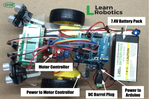
Wire gauge describes the thickness of an electrical conductor. In the American Wire Gauge (AWG) system, the numbering works in reverse: the smaller the AWG number, the thicker the wire. For example, 14 AWG wire is thicker than 18 AWG wire and generally has lower resistance over the same length.
Wire size affects three important aspects of robot performance: current-carrying capacity, voltage drop, and heat generation.
When a wire is too thin for its load, its resistance can cause a noticeable voltage drop between the battery and the motor driver. This matters particularly in low-voltage systems, where even a small loss can represent a significant portion of the available voltage. A motor may receive less voltage than expected, while a controller may reset if its supply falls below the required operating threshold.
Wire resistance also converts some electrical energy into heat. In a compact robot enclosure, where cables may be bundled together or routed near motors and electronics, excessive heating can become a reliability concern.
Different sections of a robot may therefore need different wire gauges. The main battery cable may carry the combined current of several motors, while a sensor branch carries only a small load. Sizing every wire identically can add unnecessary weight or leave critical connections undersized.
Part 2. Determine the robot’s current requirements
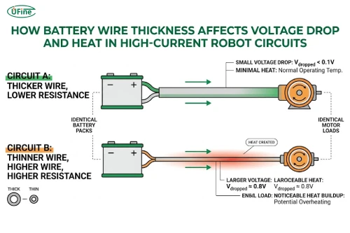
Before choosing a wire gauge, determine how much current the circuit must carry. Start with the electrical loads connected to the battery, including motor drivers, controllers, sensors, and other powered accessories.
For a device with a known electrical power demand, the basic relationship is:
Current (A) = Power (W) / Voltage (V)
For example, a 120 W load operating from a nominal 12 V supply draws approximately 10 A under the stated power assumption:
Current = 120 / 12 = 10 A
This calculation is a useful starting point, but motor-driven robots require additional consideration. Motor startup, acceleration, and mechanical resistance can produce current peaks substantially higher than normal running current. A stalled motor can draw even more current, depending on its design and the available supply.
You should distinguish between continuous current and peak current. Continuous current determines the sustained thermal demand on the wiring, while peak current helps you evaluate short-term voltage drop, connection performance, and the system’s ability to handle transients. A brief peak does not automatically make a wire suitable or unsuitable; its duration, repetition, conductor temperature, and installation conditions all matter.
When a robot has multiple motors, calculate the expected combined load under realistic operating conditions. Two motors may start simultaneously, or an actuator may operate while the drive motors are accelerating. Do not simply add every component’s maximum rated current if those conditions cannot occur together, but do not assume loads are independent without checking the control strategy.
Finally, verify that the battery, BMS, fuse, and connectors can support the required current. A thicker wire cannot compensate for a battery or protection circuit that cannot deliver the necessary power.
Part 3. Calculate voltage drop and wire resistance
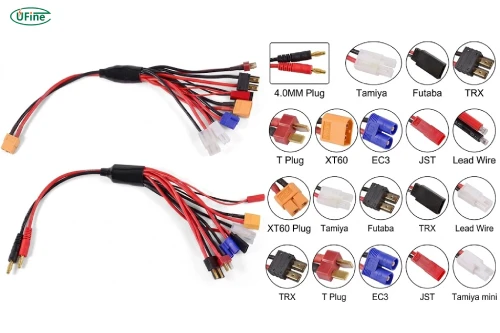
Current capacity is only one part of wire selection. You also need to determine how much voltage will be lost along the cable.
For a DC circuit, calculate voltage drop using:
Voltage drop (V) = Current (A) * Total wire resistance (ohms)
The total wire resistance must include the complete current path: the positive conductor and the negative return conductor. If the battery is 0.5 m from the motor driver, for example, the electrical path is approximately 1 m of conductor, excluding additional resistance from connectors and other components.
For a uniform conductor, resistance can be estimated using:
Wire resistance (ohms) = Resistivity * Wire length / Cross-sectional area
Here, resistivity depends on the conductor material, wire length is the length of the conductor being calculated, and cross-sectional area is the conductor’s metal area. Use consistent units throughout the calculation.
Copper is widely used in robot battery wiring because of its relatively low electrical resistance. However, resistance increases with conductor temperature, so calculations based on room-temperature values may underestimate losses when the cable becomes hot.
You can also calculate the heat generated by wire resistance:
Power loss (W) = Current (A)^2 * Resistance (ohms)
This relationship explains why a small increase in current can create a much larger increase in heating when resistance remains constant.
For example, if a complete wire path has a resistance of 0.02 ohms and carries 10 A:
Voltage drop = 10 * 0.02 = 0.20 V
Power loss = 10^2 * 0.02 = 2 W
At 12 V, a 0.20 V drop represents approximately 1.67% of the nominal supply voltage. Whether that is acceptable depends on the robot’s voltage tolerance and the requirements of the connected equipment.
A useful next step is to set a voltage-drop target for the circuit. A target of 3% may be appropriate for some designs, while more sensitive low-voltage systems may need a tighter limit. Treat any percentage as a design target, not a universal safety rule.
Part 4. Select the appropriate battery wire gauge
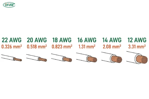
Once you understand the current demand and allowable voltage drop, compare suitable wire sizes. The following table provides common AWG sizes and their approximate conductor cross-sectional areas.
| Wire gauge | Conductor area | Typical design considerations |
|---|---|---|
| 22 AWG | 0.326 mm² | Low-current sensors and control circuits |
| 20 AWG | 0.518 mm² | Small auxiliary loads |
| 18 AWG | 0.823 mm² | Moderate-current wiring |
| 16 AWG | 1.31 mm² | Higher-current compact connections |
| 14 AWG | 2.08 mm² | Higher-current power distribution |
| 12 AWG | 3.31 mm² | Higher current or longer runs requiring lower resistance |
These descriptions are general guidance, not guaranteed current ratings. The same AWG size can have different allowable current limits depending on insulation, conductor temperature rating, ambient temperature, bundling, ventilation, and applicable electrical standards.
For example, 18 AWG wire may work for one short, moderately loaded circuit but be unsuitable for another installation carrying the same current inside a hot, tightly packed enclosure. Always check the specific wire manufacturer’s ratings and the requirements applicable to your product.
Check voltage drop before finalizing the size
After selecting a candidate wire based on current capacity, calculate its voltage drop at both continuous and representative peak current. If the drop exceeds your target, consider a thicker conductor or a shorter cable route.
For instance, reducing resistance from 0.02 ohms to 0.01 ohms in the earlier 10 A example changes the results to:
Voltage drop = 10 * 0.01 = 0.10 V
Power loss = 10^2 * 0.01 = 1 W
Both voltage drop and resistive power loss are halved.
Consider flexibility and insulation
Robots often experience vibration and repeated movement, so stranded conductors are generally more suitable than solid wires for flexible battery connections. In moving joints or compact enclosures, cable flexibility, bend radius, abrasion resistance, and strain relief are especially important.
Silicone-insulated wires may be useful when flexibility or temperature resistance is required, but the insulation type alone does not determine the allowable current. The conductor size and complete installation conditions still matter.
Part 5. Account for connectors and installation conditions
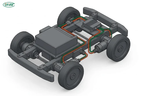
Even correctly sized wire can perform poorly if the connections are unsuitable. Battery connectors, crimp terminals, solder joints, and power-distribution contacts all contribute resistance to the circuit.
At high current, a poor connection can become a localized heating point. For example, a loose or poorly crimped terminal may heat up even when the main cable remains relatively cool. Choose connectors with appropriate current ratings, and ensure that the wire gauge matches the terminal’s specified conductor range.
Cable routing also affects performance. Measure the complete electrical path rather than only the distance from the battery to the load. Avoid unnecessary cable length, but do not make cables so short that they become strained during assembly, maintenance, or robot movement.
Heat, vibration, and mechanical stress deserve particular attention in mobile robots. Protect cables from sharp edges and moving mechanisms, secure them against repeated flexing, and use suitable strain relief near battery terminals and connectors.
The fuse and BMS must also be coordinated with the wiring. Overcurrent protection should be selected to protect the conductors while accommodating the system’s legitimate operating and transient current demands. Never increase a fuse rating simply to prevent nuisance trips without verifying that the wire and connected components remain adequately protected.
Part 6. Avoid common battery wire sizing mistakes
One common mistake is sizing wires only according to average operating current. A robot may run smoothly under normal conditions but experience excessive voltage drop when several motors accelerate simultaneously. Evaluate realistic peak-load conditions as well as continuous operation.
Another mistake is calculating resistance using only the positive wire. The negative return conductor carries the same circuit current, so ignoring it underestimates total voltage drop.
It is also risky to rely entirely on generic AWG charts. A wire’s current-carrying capacity depends on its construction and installation, not just its diameter. Similarly, selecting an unnecessarily thick wire can increase weight, assembly difficulty, and routing problems. The goal is to find a suitable size that meets both electrical and mechanical requirements.
Finally, do not overlook connectors, crimps, and solder joints. Their resistance can cause localized heating and unstable power delivery even when the cable itself is adequately sized.
Part 7. Test battery wiring under real operating conditions
Calculations provide a starting point, but testing confirms whether the selected wire works in the actual robot.
Measure voltage at the battery terminals and at the load while the robot is operating under a representative load. The difference between the two readings indicates the voltage drop across the intervening power path. Test during normal operation and during expected acceleration or other high-current events.
Check wire and connector temperatures over representative operating cycles. Pay attention to localized heating around crimps, terminals, and solder joints, and test under realistic enclosure temperatures and ventilation conditions.
Finally, verify that the robot’s motors, controllers, and sensors operate reliably. Confirm that the BMS and fuse behave as intended, and repeat the evaluation if you change the battery voltage, motor configuration, cable routing, or operating profile.
Conclusion
Selecting the right battery wire gauge for high-current robot applications requires balancing current capacity, voltage drop, heat generation, cable length, and mechanical flexibility. A lower AWG number generally means a thicker conductor with lower resistance, but wire size alone does not guarantee a safe installation.
For reliable robot battery performance, calculate the expected current, verify voltage drop, check the applicable ampacity limits, and ensure that connectors and protection devices are properly matched. Real-world testing then confirms whether the complete power system can handle the robot’s operating demands safely and consistently.
FAQs
1. Does a robot’s battery wire gauge affect motor torque?
It can. An undersized wire creates greater voltage drop under load, reducing the voltage available to the motor driver. If the motor receives insufficient voltage, its performance and available torque may be affected.
2. Can two smaller wires replace one larger battery wire?
Sometimes, but only when parallel conductors are permitted by the applicable design requirements and are installed to share current appropriately. Unequal resistance, different connection quality, and uneven routing can cause unequal current distribution. Do not assume two smaller wires automatically provide the same performance as one larger wire.
3. Is silicone wire better than PVC wire for mobile robots?
Silicone-insulated wire is often more flexible and may offer a higher temperature rating, depending on the product. PVC wire may be suitable for less demanding applications. Compare the specific wire’s temperature rating, abrasion resistance, flexibility, and installation requirements before choosing.
4. How does a robot’s duty cycle affect battery wire sizing?
Duty cycle describes how long a load operates relative to its overall operating period. It affects the wire’s thermal behavior because intermittent current may allow some cooling between operating periods. However, high-current pulses can still cause voltage drop and localized heating, so duty cycle should be evaluated alongside peak current and pulse duration.
5. Should the BMS wire gauge match the main battery cable?
Not necessarily. The appropriate wire gauge depends on the current carried by each connection and the circuit’s electrical and thermal requirements. BMS sensing wires may carry very little current, while battery discharge connections can carry much more. Follow the BMS manufacturer’s wiring specifications and ensure that all conductors are adequately protected.
Related Tags:

More Articles

How to Reduce Standby Power Drain in Battery-Powered Robots
Learn how to measure robot standby current, calculate battery drain, and optimize sensors, wireless modules, and power management.
How to Test Battery Overcurrent Protection in an Electronic Device
Want to verify battery safety? Learn how engineers test overcurrent protection, measure response time, and optimize LiPo battery performance.
AI Hardware’s Challenge: The Battery Problem
AI hardware is evolving fast, but power limitations could slow adoption. Learn how advanced lithium batteries solve the challenges of smarter devices.
How to Measure Standby Power Consumption in Battery-Powered Devices
Learn how to measure standby power, detect hidden current drain, and calculate battery life with practical testing methods for battery-powered devices.
How to Audit a Battery Manufacturer Before You Buy
Not sure if a battery supplier is reliable? Learn what to inspect, which records to request, and how to spot risks before placing an order.