- Part 1. Understanding battery overcurrent protection testing
- Part 2. Key parameters to evaluate during overcurrent testing
- Part 3. Equipment required for battery overcurrent protection testing
- Part 4. Step-by-step procedure to test battery overcurrent protection
- Part 5. Common failure modes in overcurrent protection testing
- Part 6. How to design reliable overcurrent protection for LiPo battery applications
- Part 7. Choosing a LiPo battery supplier with reliable protection solutions
- Part 8. FAQs
For engineers developing battery-powered products, overcurrent protection is one of the most important safety functions to validate. Excessive current caused by short circuits, component failures, motor startup surges, or abnormal loads can quickly increase battery temperature and damage both the battery and electronic system.
Testing battery overcurrent protection helps you confirm whether the protection circuit can detect abnormal current conditions, disconnect the load correctly, and recover safely after the fault is removed.
Key takeaways
- Overcurrent protection testing verifies whether a lithium battery protection circuit can respond correctly to excessive current conditions.
- The main parameters to evaluate include protection threshold, response time, cutoff behavior, and recovery performance.
- Electronic loads, oscilloscopes, and current measurement equipment are commonly used for testing.
- Proper overcurrent protection validation is essential for LiPo batteries used in compact consumer electronics.
Part 1. Understanding battery overcurrent protection testing
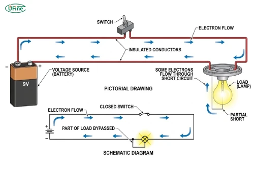
What overcurrent protection detects in lithium batteries
Battery overcurrent protection prevents lithium batteries from delivering current beyond their safe operating range.
An overcurrent event occurs when the current flowing from the battery exceeds the designed protection limit. Common causes in consumer electronics include:
- Short circuits caused by wiring failures
- Motor startup current spikes
- Damaged electronic components
- Excessive external loads
- Incorrect power system design
Unlike normal operating current, overcurrent conditions can create rapid heat generation and accelerate battery degradation.
For example, a wearable device may operate normally at 500mA but experience a sudden 5A current surge if a component fails. Without protection, this abnormal current can damage the battery cell or protection components.
How battery overcurrent protection works
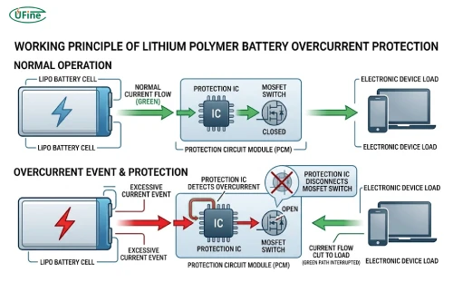
Most lithium polymer batteries use a protection circuit module (PCM) or battery management system (BMS) to monitor current flow.
The basic protection structure includes:
ComponentFunctionProtection ICDetects abnormal current conditionsMOSFET switchDisconnects battery output during protectionCurrent sensing circuitMeasures current changesBattery cellProvides power to the device
When excessive current is detected:
- The protection IC monitors current increase.
- The protection threshold is exceeded.
- The IC sends a signal to the MOSFET.
- The MOSFET disconnects the battery output.
- The device power supply is interrupted to prevent damage.
For compact consumer electronics, the protection design must balance safety and usability. If the protection threshold is too low, normal device operation may be interrupted. If it is too high, the battery may not be adequately protected.
Part 2. Key parameters to evaluate during overcurrent testing
When testing battery overcurrent protection, engineers should focus on several electrical parameters.
Overcurrent protection threshold
The overcurrent threshold is the current value at which the protection circuit activates.
A suitable threshold depends on:
- Battery capacity
- Discharge rate
- Device operating current
- Peak current demand
The maximum continuous discharge current can be estimated using:
Maximum discharge current (A)
= Battery capacity (Ah) × Discharge rate (C)
Example:
A 1000mAh LiPo battery with a 5C discharge rating:
1Ah × 5C = 5A
This means the battery can theoretically provide 5A continuous current under specified conditions.
During testing, you should verify that:
- The protection activates within the designed range.
- Normal operating current does not trigger protection.
- Peak current demand does not cause unnecessary shutdown.
Protection response time
Response time measures how quickly the protection circuit disconnects the battery after detecting excessive current.
A fast response is especially important for:
- Portable medical devices
- Wearable electronics
- IoT products
- High-power handheld devices
Engineers typically measure:
- Current rise time
- Detection delay
- MOSFET shutdown time
An oscilloscope with a current probe can capture the complete protection waveform.
Cutoff behavior and voltage response
During an overcurrent event, you should monitor:
- Output voltage drop
- Current cutoff point
- Battery recovery voltage
A properly functioning protection circuit should quickly stop current flow and prevent continuous overheating.
Recovery characteristics
After protection activates, the recovery behavior should also be tested.
Common recovery methods include:
- Automatic recovery after removing the abnormal load
- Recovery after reconnecting a charger
- Permanent latch protection requiring manual reset
Testing recovery performance helps ensure the device can return to normal operation after temporary faults.
Part 3. Equipment required for battery overcurrent protection testing
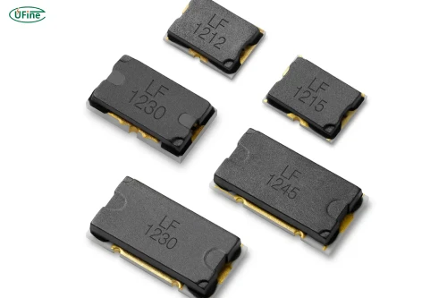
Reliable testing requires proper measurement equipment.
Programmable electronic load
A programmable electronic load is the primary tool for simulating different current conditions.
It allows engineers to:
- Increase current gradually
- Apply overload conditions
- Simulate real device power demand
- Record current cutoff points
For example, you can increase the load from the normal operating current until the battery protection circuit activates.
Oscilloscope and current measurement tools
An oscilloscope helps capture the exact moment when protection activates.
You can measure:
- Current spike waveform
- Protection delay time
- Voltage interruption point
This data is useful when optimizing PCM or BMS parameters.
Temperature monitoring equipment
Temperature measurement is important because excessive current often creates thermal stress.
Monitor:
- Battery surface temperature
- Protection circuit temperature
- Temperature increase during overload
A battery that repeatedly reaches high temperatures during testing may require a different protection design or battery specification.
Part 4. Step-by-step procedure to test battery overcurrent protection
Step 1. Review battery protection specifications
Before testing, confirm the battery specifications:
- Nominal voltage
- Capacity
- Continuous discharge current
- Peak discharge current
- Overcurrent protection threshold
- PCM/BMS specifications
Understanding these values helps you define safe testing limits.
Step 2. Connect the battery to the electronic load
The basic test setup is:
LiPo Battery
↓
Protection Circuit
↓
Electronic Load
Before applying current:
Record:
- Initial battery voltage
- Ambient temperature
- Battery condition
- Test equipment settings
Step 3. Increase current gradually
Do not immediately apply extreme current.
A typical test process:
| Current condition | Expected result |
|---|---|
| Normal operating current | Battery operates normally |
| Peak operating current | Stable output |
| Overcurrent threshold | Protection activates |
| Excessive current | Output disconnects |
During testing, monitor:
- Current value
- Battery voltage
- Protection activation point
- Temperature change
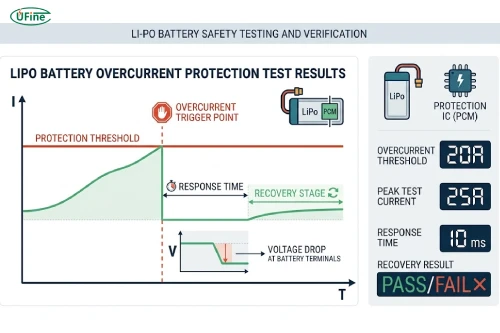
Step 4. Record protection activation data
Important test results include:
- Trigger current (A)
- Response time (ms)
- Cutoff voltage
- Recovery behavior
- Temperature rise
These results can be compared with design requirements.
Step 5. Verify recovery performance
After protection activation:
- Remove the overload condition.
- Wait for recovery.
- Reconnect the load.
- Repeat multiple cycles.
A reliable protection system should recover consistently without abnormal heating or performance loss.
Part 5. Common failure modes in overcurrent protection testing
During overcurrent protection testing, unexpected results usually indicate problems with battery selection, protection circuit design, or system integration. Identifying these issues early can prevent failures during product validation.
Protection activates below the expected current
If the battery protection circuit disconnects power before reaching the expected current level, possible causes include:
- Incorrect overcurrent protection threshold
- Battery discharge capability is insufficient
- High internal resistance inside the battery cell
- Excessive voltage drop across the protection MOSFET
For example, a high-power consumer device may require short-duration peak current during startup. If the battery protection current rating is too low, the device may repeatedly shut down even though the battery itself is not damaged.
Possible solutions include:
- Selecting a LiPo battery with a higher discharge rate
- Adjusting PCM protection parameters
- Using lower-resistance MOSFET components
- Optimizing the device power circuit
Protection fails to activate
If the protection circuit does not disconnect the load during excessive current conditions, it may create a serious safety risk.
Common causes include:
- Damaged protection IC
- Failed MOSFET switch
- Incorrect circuit connection
- Protection threshold set too high
- Faulty current sensing components
To troubleshoot this issue, engineers should verify:
- PCM wiring configuration
- Protection IC operation
- Current measurement accuracy
- Battery output behavior during overload
Excessive voltage drop before protection activates
A significant voltage drop during high-current testing often indicates that the battery system cannot support the required power demand.
Possible reasons include:
- High battery internal resistance
- Undersized battery capacity
- Poor connector design
- Insufficient discharge capability
For compact electronic devices, selecting a battery with suitable discharge performance is essential because voltage instability can cause device resets or unexpected shutdowns.
Part 6. How to design reliable overcurrent protection for LiPo battery applications
Overcurrent protection should be considered during battery selection and product design, not only during final testing.
Match battery discharge capability with device current demand
The battery should support both normal and peak current requirements.
When selecting a LiPo battery, consider:
- Average operating current
- Maximum peak current
- Startup surge current
- Operating environment
- Required battery lifespan
For example, smart wearable devices may have low average power consumption but experience short current peaks from wireless communication modules or motors.
A battery designed only for average current may experience repeated protection activation during peak loads.
Select suitable PCM or BMS protection parameters
The protection circuit should match the application requirements.
Important parameters include:
- Overcurrent protection current
- Short circuit protection current
- MOSFET current rating
- Response time
- Thermal performance
A properly designed protection system should provide safety without limiting normal device performance.
For customized LiPo battery applications, manufacturers can adjust protection parameters based on:
- Device power requirements
- Battery size limitations
- Expected discharge profile
- Safety certification requirements
Validate protection performance during prototype testing
Before mass production, engineers should perform multiple validation tests, including:
- Maximum load testing
- Repeated overload testing
- Short circuit protection testing
- High-temperature overload testing
- Real application scenario testing
Testing under realistic conditions helps identify problems that may not appear during standard laboratory measurements.
Part 7. Choosing a LiPo battery supplier with reliable protection solutions
For consumer electronics, battery protection performance depends not only on the protection circuit but also on battery cell quality, manufacturing consistency, and engineering support.
A reliable lithium polymer battery manufacturer should be able to provide:
- Customized PCM protection solutions
- Different discharge current options
- Battery design optimization
- Safety testing support
- Prototype and mass production services
Ufine Battery provides customized LiPo battery solutions for consumer electronics, including flexible battery dimensions, customized capacity, voltage options, and protection circuit designs. By matching battery performance with device requirements, engineers can improve product reliability and reduce development risks.
Ufine Battery can customize capacity, voltage, protection solutions, and dimensions to meet your specifications — whether for prototype testing or volume production.
Find A Solution NowPart 8. FAQs
1. Can a higher-capacity battery solve overcurrent protection issues?
Not always. Battery capacity mainly affects runtime, while overcurrent capability depends on factors such as discharge rate, cell chemistry, internal resistance, and protection circuit design. A higher-capacity battery may still trigger protection if its discharge capability is insufficient.
2. Does battery temperature affect overcurrent protection performance?
Yes. High temperature can affect battery internal resistance, protection component performance, and safety limits. Overcurrent testing should evaluate protection behavior under different temperature conditions, especially for devices used in demanding environments.
3. Can firmware prevent battery overcurrent events?
Firmware can help reduce unnecessary overcurrent conditions by controlling power consumption, limiting motor startup current, and managing peak loads. However, firmware cannot replace hardware-based battery protection circuits because electrical faults can occur even when software is functioning normally.
4. Why does a battery pass laboratory testing but fail in the final device?
A battery may pass standalone testing but fail after integration because the actual device creates different current patterns. Factors such as motor startup, wireless transmission peaks, charging behavior, and PCB design can change real-world current demand.
5. What is the difference between battery overcurrent protection and overcharge protection?
Overcurrent protection manages excessive current during discharge or abnormal load conditions, while overcharge protection prevents the battery voltage from exceeding safe charging limits. Both are important parts of lithium battery safety design but protect against different risks.
Related Tags:

More Articles

AI Hardware’s Challenge: The Battery Problem
AI hardware is evolving fast, but power limitations could slow adoption. Learn how advanced lithium batteries solve the challenges of smarter devices.
How to Measure Standby Power Consumption in Battery-Powered Devices
Learn how to measure standby power, detect hidden current drain, and calculate battery life with practical testing methods for battery-powered devices.
How to Audit a Battery Manufacturer Before You Buy
Not sure if a battery supplier is reliable? Learn what to inspect, which records to request, and how to spot risks before placing an order.
How to Route Battery Wires in a Compact Electronic Enclosure
Routing battery wires in tight spaces? Learn how to prevent pinched cables, voltage drop, insulation damage, and costly electronic failures.
How to Match Battery Discharge Current to Motor Startup Demand
Does your motor struggle to start? Learn how to calculate startup current, prevent voltage drop, and choose a battery that delivers reliable power.