- Key takeaways
- Part 1. What is battery discharge current?
- Part 2. Why do motors draw more current during startup?
- Part 3. How to calculate battery discharge current for motor startup
- Part 4. How voltage drop affects motor startup
- Part 5. How to choose a LiPo battery for motor startup demand
- Part 6. How to test battery discharge current under real conditions
- Part 7. How to troubleshoot motor startup failure
- Part 8. How custom LiPo battery design supports motor-driven devices
- Part 9. FAQs
A battery that can power a motor during normal operation may still fail to start it. The reason is that motors often draw a much higher current during startup than they do once they reach their operating speed. If the battery, battery management system (BMS), or wiring cannot handle this temporary demand, the motor may start slowly, the controller may reset, or the battery protection circuit may disconnect the power.
Texas Instruments illustrates this difference in its motor-control engineering guidance: one brushed DC motor can draw a startup peak above 14 A without current regulation, even though its steady-state current is below 1 A. This demonstrates why selecting a battery based only on a motor’s rated running current can lead to problems. Source: Texas Instruments
For battery-powered devices such as robotics, smart locks, portable equipment, and automated mechanisms, matching battery discharge current to motor startup demand is essential. This guide explains how to identify startup current, estimate battery requirements, evaluate voltage drop, and verify performance under real operating conditions.
Key takeaways
- Motor startup current can be several times higher than its normal running current.
- Rated current, startup current, and stall current describe different operating conditions.
- Battery capacity (mAh or Ah) alone does not determine whether a battery can deliver enough current.
- Battery voltage drop, internal resistance, BMS limits, connectors, and wiring all affect startup performance.
- Peak current and its duration must both be considered when selecting a LiPo battery.
- Real-world testing under low-charge, low-temperature, and loaded conditions helps verify a reliable design.
Part 1. What is battery discharge current?
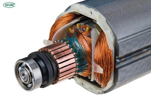
Battery discharge current is the electrical current a battery supplies to a connected device. It is measured in amperes (A). For motor-driven equipment, two specifications are particularly important.
Continuous discharge current is the current a battery can supply within its specified operating limits over an extended period.
Peak discharge current is a higher current permitted for a limited time. The manufacturer should specify both the allowable current and the duration. A battery rated for a 10 A peak, for example, cannot automatically be assumed to support 10 A indefinitely.
Battery capacity and discharge current are also different. A 2,000 mAh battery stores 2 Ah of charge, but that capacity alone does not tell you whether the battery can deliver a 5 A startup pulse. You must check the cell’s discharge rating, internal resistance, and protection circuitry.
For LiPo batteries, the C-rate provides another reference. The theoretical current is calculated as:
I=C-rate×capacity (Ah)
A 2 Ah battery rated at 5C would have a calculated discharge current of 10 A. However, this figure is only valid if the battery manufacturer permits that rate under the relevant conditions. Peak limits, temperature, battery age, and BMS restrictions still apply.
Part 2. Why do motors draw more current during startup?
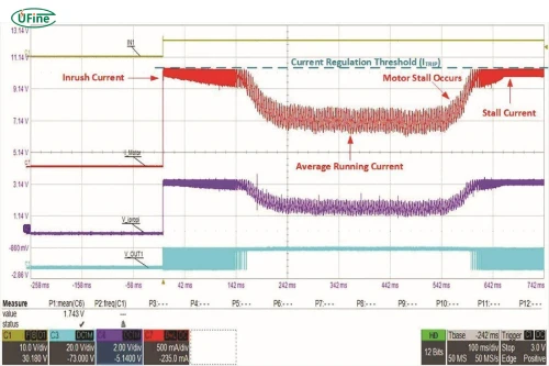
When a motor starts from rest, it must overcome inertia, friction, and the load attached to its shaft. At the same time, the motor has not yet developed its normal rotational speed.
In a brushed DC motor, rotation generates back electromotive force (back EMF), which opposes the applied voltage. At startup, the motor is stationary, so back EMF is initially close to zero. This allows current to rise sharply, limited mainly by winding resistance and the rest of the electrical circuit.
As the motor accelerates, back EMF increases and current generally falls toward its normal operating level.
The exact startup profile depends on the motor type and control system:
- Brushed DC motors: Often have a pronounced inrush current when started directly.
- Brushless DC (BLDC) motors: Startup current depends on the motor controller, commutation strategy, current limits, and mechanical load.
- Motors under heavy load: May need more torque and remain at high current for longer.
- Stalled motors: Can continue drawing excessive current if the controller does not limit or interrupt it.
Startup current is not always the same as stall current. Stall current describes the current when the motor is prevented from rotating under the specified test conditions. It can be useful as a conservative reference for some designs, but the actual startup current depends on the driver, supply voltage, and current-limiting behavior.
Part 3. How to calculate battery discharge current for motor startup
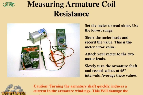
The first step is to identify the motor’s actual electrical requirements. Check its datasheet for the following values:
- Rated current: Current under specified normal operating conditions.
- No-load current: Current when the motor runs without its intended mechanical load.
- Startup or inrush current: Current drawn as the motor begins rotating.
- Stall current: Current when the motor cannot rotate under the specified conditions.
- Controller-limited current: The maximum current permitted by the motor driver or control system.
Do not assume that rated current equals startup current. If the datasheet does not list startup current, ask the motor manufacturer or measure the current during startup.
For a brushed DC motor, a simplified estimate of the initial current is:
I_start ≈ V / R
Here, Vis the voltage applied to the motor and Ris its winding resistance. This estimate assumes negligible back EMF at zero speed and does not account for all circuit resistance or controller current limiting. It is not a universal formula for BLDC motors.
You can also estimate normal running current from electrical input power:
I_run ≈ P_in / V
For example, a 12 V motor consuming 24 W of electrical input power draws approximately 2 A during that operating condition. However, this calculation does not establish its startup current.
Suppose the motor datasheet specifies an 8 A startup peak lasting 0.3 seconds. Your battery system must support that pulse without excessive voltage drop, BMS cutoff, or damage to the motor driver.
Part 4. How voltage drop affects motor startup
Supplying enough current is only part of the problem. The battery must also maintain sufficient voltage while the motor starts.
When current flows through the battery’s internal resistance, the terminal voltage drops. A simplified estimate is:
V_load ≈ V_OC – I × R_int
Where:
- V_load is the battery voltage under load.
- V_OC is the open-circuit voltage.
- I is the discharge current.
- Rint is the battery’s effective internal resistance.
Consider a battery with an open-circuit voltage of 12 V and an effective internal resistance of 40 mΩ. At an 8 A startup current:
ΔV=8×0.040=0.32 V
The estimated battery terminal voltage is therefore 11.68 V. This simplified calculation excludes additional voltage drops across the BMS, motor driver, wiring, and connectors.
If the voltage at the motor driver falls below its undervoltage threshold, the controller may reset or stop driving the motor. A weak connection or undersized wire can worsen the problem.
This is why a battery that meets the current requirement on paper may still fail in the finished device. The voltage at the load during startup matters just as much as the battery’s nominal specifications.
Part 5. How to choose a LiPo battery for motor startup demand
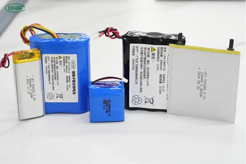
When selecting a lithium polymer battery, evaluate the complete power system rather than relying on capacity alone.
| Selection factor | What to check |
|---|---|
| Continuous discharge current | Must support the motor’s sustained operating current. |
| Peak discharge current | Must cover startup current for the required duration. |
| Voltage and configuration | Must match the motor driver’s operating range. |
| Internal resistance | Lower resistance generally reduces voltage sag. |
| BMS and protection | Overcurrent limits and delay settings must suit the startup profile. |
| Wiring and connectors | Must safely carry the expected current with acceptable voltage drop. |
| Operating conditions | Check performance at low charge, low temperature, and after aging. |
The C-rate is useful for an initial check, but manufacturer-approved current limits take priority. Also confirm whether the quoted peak current applies to the cell, the assembled battery pack, or the protected pack output.
Series and parallel configurations affect current capability differently. Connecting cells in series increases pack voltage but does not automatically increase the current capability beyond the limits of the individual series cells. Connecting suitable cells in parallel can increase available current and reduce equivalent internal resistance, but actual performance depends on cell matching, interconnections, temperature, and protection circuitry.
For repeated motor starts, consider both the peak current and how often it occurs. A single 0.3-second pulse is different from repeated starts every few seconds. The I²t value can help compare current-related stress:
I²t = ∫ I² dt
For a constant 8 A pulse lasting 0.3 seconds,I²t = 19.2 A²·s. This is a useful reference, not a standalone method for predicting battery temperature or proving that a pack is safe. Manufacturer limits and thermal testing remain essential.
Part 6. How to test battery discharge current under real conditions
Calculations and datasheets establish a starting point, but testing helps verify that the battery performs reliably in the actual device.
A practical test procedure is:
- Measure startup current. Use a suitable current probe or a properly designed shunt-resistor measurement system with an oscilloscope or data logger.
- Record voltage at the same time. Measure battery terminal voltage during startup and, where practical, the voltage at the motor driver.
- Capture the full pulse. Record peak current, pulse duration, and minimum voltage rather than relying on a single displayed reading.
- Repeat under realistic conditions. Test at different states of charge, temperatures, mechanical loads, and expected startup frequencies.
- Check protection behavior. Confirm that the BMS and motor driver do not disconnect or enter fault mode during normal startup.
Choose instruments with suitable current range, bandwidth, and sampling capability. A basic multimeter may miss a brief current peak, and inserting an unsuitable meter into a high-current circuit can introduce resistance or create a safety hazard.
Do not deliberately stall a motor for extended periods unless the motor and test setup are designed for it. High stall current can overheat the winding, driver, wiring, and battery.
Part 7. How to troubleshoot motor startup failure
If a motor fails to start consistently, investigate the complete electrical and mechanical system.
| Symptom | Possible cause | What to check |
|---|---|---|
| Motor does not start | Insufficient startup current or excessive mechanical load | Motor datasheet, battery current limits, and mechanism friction |
| Controller resets at startup | Excessive voltage sag | Battery voltage under load, internal resistance, wiring, and connectors |
| BMS disconnects | Overcurrent threshold or permitted pulse duration exceeded | BMS specifications and startup-current waveform |
| Motor starts intermittently | Low state of charge, temperature, loose connection, or varying load | Repeat tests under different operating conditions |
| Battery or wiring heats excessively | Excessive current or resistance | Connections, wire sizing, current profile, and component ratings |
These symptoms are diagnostic clues, not definitive conclusions. For example, a controller reset can result from voltage sag at the battery or from a voltage drop elsewhere in the circuit.
If the battery becomes unusually hot, swells, leaks, or shows other signs of damage, stop using it and follow the manufacturer’s safety guidance.
Part 8. How custom LiPo battery design supports motor-driven devices
For compact products such as robotics, smart locks, portable actuators, and intelligent hardware, standard batteries may not provide the right combination of dimensions, voltage, current capability, and runtime.
A custom LiPo battery solution can be designed around the device’s measured power profile. Important considerations include cell selection, series-parallel configuration, allowable peak-current duration, internal resistance, BMS settings, connector type, and available installation space.
Ufine Battery provides customized lithium battery solutions for applications with specific size and electrical requirements. When developing a motor-powered product, share the motor’s startup and running current, required voltage, startup duration, operating temperature range, and expected number of starts. These details help the battery manufacturer evaluate a suitable configuration instead of selecting a battery based on capacity alone.
The final design should be validated as a complete system, including the battery pack, protection circuit, wiring, motor driver, and motor.
Part 9. FAQs
1. Does motor startup current change with mechanical load?
Yes. A heavier load can require more torque and keep the motor at high current for longer. The actual startup profile depends on the motor, load inertia, supply voltage, and controller settings.
2. How does battery aging affect motor startup performance?
As a battery ages, its internal resistance may increase and its ability to deliver high current may decline. This can cause greater voltage sag, making startup less reliable even when the battery still appears to have usable capacity.
3. Can a longer wire cause a motor to fail to start?
Yes. Longer or undersized wires add resistance, causing additional voltage drop under high startup current. Check wire gauge, cable length, connector resistance, and the voltage available at the motor driver.
4. Does a higher C-rate always mean a better battery for motor applications?
No. A higher C-rate can indicate greater current capability relative to capacity, but it does not guarantee lower voltage sag, longer service life, or better low-temperature performance. Compare the manufacturer’s discharge limits and application-specific test data.
5. Can two batteries with the same voltage and capacity deliver different startup currents?
Yes. They may use different cells, internal resistance levels, protection circuits, and interconnections. These differences affect peak-current capability and voltage stability during motor startup.
Related Tags:

More Articles

How to Route Battery Wires in a Compact Electronic Enclosure
Routing battery wires in tight spaces? Learn how to prevent pinched cables, voltage drop, insulation damage, and costly electronic failures.
Battery Gets Hot While Fast Charging? Here’s What to Do
Does your LiPo battery get hot during fast charging? Discover the main causes, warning signs, and practical ways to reduce overheating.
Dead Battery or Device Failure? How to Find the Cause
Think your device is broken? Learn how to tell if the problem comes from battery aging or hardware failure before replacing your electronics.
Why iPhone Duo Uses Two Batteries: The Engineering Behind Foldable Phone Power
Why do foldable phones need two batteries? Explore the engineering challenges behind iPhone Duo’s dual-battery architecture and future battery trends.
Solid-State Batteries: 3 Myths You Need to Know
Solid-state batteries promise safer EVs and longer range, but the reality is more complex. Discover the challenges behind this next-gen technology.