- Key Takeaways
- Part 1. Lifepo4 battery voltage range and key terms
- Part 2. Lifepo4 voltage chart by state of charge
- Part 3. 3.2v, 12v, 24v and 51.2v lifepo4 voltage charts
- Part 4. Lifepo4 charging voltage chart and charger settings
- Part 5. Lifepo4 bulk, float and equalize voltage
- Part 6. How to read a lifepo4 soc chart accurately
- Part 7. Lifepo4 internal resistance chart and voltage sag
- Part 8. Factors affecting lifepo4 battery voltage
- Part 9. Choosing the right lifepo4 battery voltage for applications
- Part 10. Lifepo4 battery voltage problems and troubleshooting
- Part 11. Lifepo4 voltage chart FAQs
A LiFePO4 voltage chart helps you estimate battery state of charge, select charger settings, diagnose voltage drops, and match a battery with an electrical system. However, LiFePO4 batteries have a flat discharge curve, so voltage alone cannot show the exact remaining capacity.
This guide covers the typical voltage values for a 3.2V LiFePO4 cell and common 12V, 24V, and 48V-class battery packs. It also explains LiFePO4 charging voltage, SOC measurement, internal resistance, and BMS settings.
Key Takeaways
- A LiFePO4 cell has a nominal voltage of about 3.2V.
- A fully charged cell normally reaches 3.60–3.65V during charging.
- A 12V LiFePO4 battery usually uses four cells in series and has a nominal voltage of 12.8V.
- A 24V LiFePO4 battery usually uses eight cells in series and has a nominal voltage of 25.6V.
- A 48V-class LiFePO4 battery commonly uses 16 cells in series and has a nominal voltage of 51.2V.
- LiFePO4 voltage changes very little between about 20% and 90% SOC.
- Resting voltage gives a better SOC estimate than voltage measured during charging or under load.
- Use the battery datasheet, charger specification, and BMS limits when setting voltage thresholds.
Part 1. Lifepo4 battery voltage range and key terms
The LiFePO4 voltage range depends on whether the battery is charging, resting, discharging, or reaching a protection limit. A single voltage value should therefore be interpreted together with current, temperature, and operating condition.
For a broader comparison with NMC, LiPo, LCO, and other lithium chemistries, see this lithium battery voltage comparison by chemistry.
LiFePO4 nominal voltage
The nominal LiFePO4 cell voltage is normally 3.2V. Nominal voltage is a reference value used to describe the battery system. It is not the full-charge voltage.
| Battery Configuration | Cells in Series | Nominal Voltage |
|---|---|---|
| Single LiFePO4 cell | 1S | 3.2V |
| 12V LiFePO4 battery | 4S | 12.8V |
| 24V LiFePO4 battery | 8S | 25.6V |
| 48V-class LiFePO4 battery | 16S | 51.2V |
LiFePO4 fully charged voltage
A LiFePO4 cell normally reaches 3.60–3.65V near the end of charging. After charging stops and the battery rests, the cell voltage usually settles below this level.
The maximum charging voltage must come from the cell and battery-pack specifications. Do not assume that every LiFePO4 product uses the same upper limit.
LiFePO4 discharge cutoff voltage
Many LiFePO4 cell specifications use approximately 2.5V per cell as a technical discharge cutoff. However, this is a protection boundary rather than an ideal daily operating target.
A practical system normally disconnects the load earlier. This reduces deep discharge and prevents a weak cell from reaching its minimum voltage before the rest of the pack.
LiFePO4 storage voltage
LiFePO4 batteries should be stored at a partial state of charge rather than held continuously at maximum charging voltage. The correct storage SOC, inspection interval, and temperature depend on the battery manufacturer.
For more detail on full-charge, float, and storage behavior, read the LiFePO4 charge and float voltage guide.
Part 2. Lifepo4 voltage chart by state of charge
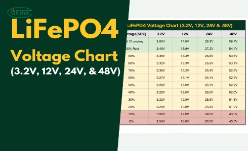
The following LiFePO4 state of charge chart shows typical open-circuit voltage values. Disconnect the battery from major charging and discharging currents before measurement. Let it rest for at least 30 minutes for a more stable reading.
| State of Charge | 3.2V Cell | 12.8V Battery | 25.6V Battery | 51.2V Battery |
|---|---|---|---|---|
| 100% while charging | 3.65V | 14.6V | 29.2V | 58.4V |
| 100% rested | 3.40V | 13.6V | 27.2V | 54.4V |
| 90% | 3.35V | 13.4V | 26.8V | 53.6V |
| 80% | 3.32V | 13.3V | 26.6V | 53.1V |
| 70% | 3.30V | 13.2V | 26.4V | 52.8V |
| 60% | 3.27V | 13.1V | 26.2V | 52.3V |
| 50% | 3.26V | 13.0V | 26.1V | 52.2V |
| 40% | 3.25V | 13.0V | 26.0V | 52.0V |
| 30% | 3.22V | 12.9V | 25.8V | 51.5V |
| 20% | 3.20V | 12.8V | 25.6V | 51.2V |
| 10% | 3.00V | 12.0V | 24.0V | 48.0V |
| Technical cutoff zone | 2.50V | 10.0V | 20.0V | 40.0V |
Note: These are approximate rested voltage values. Cell design, temperature, battery age, measurement accuracy, and rest time can change the result. Use the battery manufacturer’s SOC data when available.
The small voltage difference between 20% and 90% SOC explains why a LiFePO4 SOC chart cannot provide the same accuracy as a shunt-based battery monitor.
Part 3. 3.2v, 12v, 24v and 51.2v lifepo4 voltage charts
3.2V LiFePO4 voltage chart for a single cell
A single LiFePO4 cell has a nominal voltage of 3.2V and normally charges to 3.60–3.65V. Its voltage remains close to 3.2–3.3V through much of the discharge cycle before falling more quickly near empty.
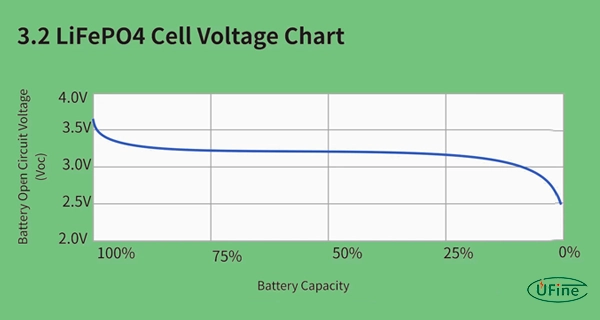
Small cells used in portable products may have different current, temperature, and cutoff limits from large prismatic cells. Check the specific model before setting the charger or BMS. Ufine provides custom 3.2V LiFePO4 cells in different sizes and capacities.
12V LiFePO4 voltage chart for a 4S battery
A 12V LiFePO4 battery normally uses four cells in series. This creates a nominal voltage of 12.8V and a maximum charging voltage of up to 14.6V.
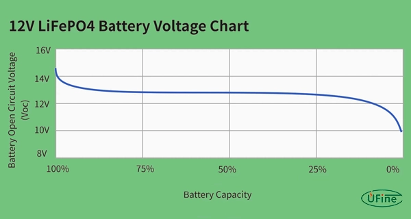
Do not set the normal low-voltage disconnect at the absolute 10.0V cell limit unless the battery manufacturer allows it. A higher system cutoff provides more margin for voltage sag and cell imbalance. See available 12V LiFePO4 battery configurations for application-specific options.
24V LiFePO4 voltage chart for an 8S battery
A 24V LiFePO4 battery usually contains eight cells in series. Its true nominal voltage is 25.6V, while its upper charging limit is up to 29.2V.
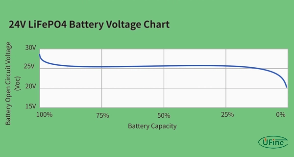
Before using a 24V LiFePO4 battery pack, confirm the charger, motor controller, inverter, and DC equipment can accept the full charging voltage.
51.2V LiFePO4 voltage chart for a 48V-class battery
Most 48V-class LiFePO4 batteries used in energy storage and industrial systems contain 16 cells in series. Their true nominal voltage is 51.2V, and their upper charging voltage is up to 58.4V.
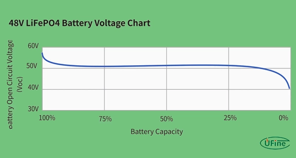
“48V” is often a system category rather than the exact nominal voltage. Some equipment may use a different series configuration. Confirm the inverter input range, BMS communication, and charger profile before selecting a 48V LiFePO4 battery solution.
Part 4. Lifepo4 charging voltage chart and charger settings
LiFePO4 batteries normally use a constant-current and constant-voltage charging method, also called CC-CV charging.
- Constant-current stage: The charger supplies a controlled current while battery voltage rises.
- Constant-voltage stage: The charger holds the target voltage while current decreases.
- Charge termination: Charging ends when current falls to the specified level or the charger completes its programmed cycle.
| Battery System | Series Count | Nominal Voltage | Typical Charging Range | Upper Limit at 3.65V/Cell |
|---|---|---|---|---|
| 3.2V cell | 1S | 3.2V | 3.55–3.65V | 3.65V |
| 12V class | 4S | 12.8V | 14.2–14.6V | 14.6V |
| 24V class | 8S | 25.6V | 28.4–29.2V | 29.2V |
| 48V class | 16S | 51.2V | 56.8–58.4V | 58.4V |
The highest value is not always the best daily charging setting. Some systems use a lower voltage to reduce time at a high SOC. Other battery packs must periodically reach a higher voltage so the BMS can balance the cells.
For example, the official Victron LiFePO4 charging parameters recommend 14.2V absorption and 13.5V float for its 12.8V battery system. These settings are specific to Victron batteries and should not replace the datasheet for another product.
If you plan to use an adjustable DC source, follow the step-by-step guide for charging a LiFePO4 battery with a power supply.
How to set LiFePO4 charging voltage
- Confirm the number of cells connected in series.
- Check the cell, battery-pack, charger, and BMS specifications.
- Use the lowest permitted upper limit if the specifications differ.
- Confirm whether the BMS requires a minimum voltage for cell balancing.
- Do not exceed the maximum voltage of any individual cell.
- Verify the charger output with a calibrated multimeter.
A properly selected battery management system for lithium batteries monitors individual cell voltage, pack voltage, current, temperature, and cell balance. Total pack voltage alone cannot identify every weak or unbalanced cell.
Part 5. Lifepo4 bulk, float and equalize voltage
LiFePO4 bulk voltage
Bulk charging is the stage in which the charger supplies controlled current and the battery voltage rises. Most of the energy is restored during this stage.
LiFePO4 absorption voltage
When the battery reaches the target voltage, the charger holds that voltage while the charging current falls. This stage completes charging and may provide time for passive cell balancing.
The required absorption time depends on the battery, charging current, BMS balancing method, and manufacturer settings.
LiFePO4 float voltage
LiFePO4 batteries do not require continuous float charging in the same way as lead-acid batteries. A compatible charger may stop charging or reduce its output to a lower standby voltage.
If a float setting is required, use the battery manufacturer’s value. Do not hold the battery continuously at its maximum charging voltage.
LiFePO4 equalize voltage
Do not use lead-acid equalization or desulfation mode with a LiFePO4 battery. These modes may apply a voltage that exceeds the battery or BMS limit.
Lithium cell balancing is not the same as lead-acid equalization. Cell balancing is controlled by the BMS or a dedicated balancing circuit.
Part 6. How to read a lifepo4 soc chart accurately
Measure the battery at rest
Disconnect major loads and charging sources. Wait at least 30 minutes before measuring open-circuit voltage. A longer rest period may provide a more stable result after high-current use.
Check individual LiFePO4 cell voltage
A normal pack voltage does not prove that every cell is healthy. Use BMS data to compare the highest cell voltage, lowest cell voltage, and total cell-voltage difference.
Measure at a known temperature
Low temperature increases internal resistance and voltage sag. Compare SOC readings taken at similar temperatures whenever possible.
Use a battery monitor for accurate SOC
Because LiFePO4 voltage remains flat through most of the discharge cycle, a shunt-based coulomb counter provides a better SOC estimate than voltage alone.
The RELiON guidance on LiFePO4 state of charge also recommends using a battery indicator that measures real-time and accumulated battery data.
Part 7. Lifepo4 internal resistance chart and voltage sag
There is no single LiFePO4 internal resistance chart that applies to every cell. Internal resistance changes with cell size, capacity, construction, SOC, temperature, age, and test method.
For example, a large prismatic energy-storage cell may have much lower resistance than a small cylindrical or pouch cell. AC resistance measured at 1kHz also cannot be compared directly with resistance calculated from a DC load test.
The most useful comparison is between cells of the same model tested under the same conditions.
| Resistance or Voltage Pattern | Possible Cause | Recommended Check |
|---|---|---|
| One cell has higher resistance than similar cells | Cell aging, damage, imbalance, or poor connection | Retest the cell and inspect terminals or welds |
| All cells show more voltage sag in cold conditions | Temporary resistance increase at low temperature | Retest at the specified operating temperature |
| Cell resistance is normal but pack resistance is high | Cable, fuse, busbar, connector, or contactor resistance | Measure voltage drop across each connection under load |
| Resistance rises while runtime falls | Battery aging or internal degradation | Compare with baseline data and run a capacity test |
| Voltage falls sharply only at peak current | Battery or connection path is undersized | Reduce current or improve battery and cable sizing |
Voltage sag can be estimated with the following relationship:
Voltage drop = Load current × Internal resistance
Higher current or higher resistance creates a larger voltage drop. It also generates more heat and may trigger the BMS earlier.
For more testing detail, see the guide to measuring lithium battery internal resistance.
Part 8. Factors affecting lifepo4 battery voltage
| Factor | Effect on LiFePO4 Voltage | Engineering Consideration |
|---|---|---|
| State of charge | Voltage falls as stored capacity decreases | Voltage is least precise through the flat middle range |
| Temperature | Cold conditions increase resistance and voltage sag | Follow the specified charging and discharging temperatures |
| Load current | Higher discharge current lowers terminal voltage | Size the battery, cables, and connectors for peak load |
| Charging current | Higher current raises terminal voltage during charging | Do not judge full SOC from charging voltage alone |
| Cell balance | One cell may reach a limit before the full pack | Check individual cell voltage through the BMS |
| Battery age | Aged cells may show greater voltage sag | Track capacity and resistance over time |
| Connection resistance | Cables and terminals create extra voltage loss | Measure voltage at both the battery and the load |
| Meter accuracy | Small errors can create a large SOC error | Use a calibrated meter for important measurements |
Part 9. Choosing the right lifepo4 battery voltage for applications
Selecting a LiFePO4 battery requires more than matching the nominal voltage shown on the equipment label. The charger, controller, inverter, DC-DC converter, peak current, and maximum input voltage must all be compatible.
| Application | Common LiFePO4 Voltage | Key Selection Points |
|---|---|---|
| Portable electronics | 3.2V or custom series pack | Size, peak current, connector, PCM, and charger design |
| RV and marine auxiliary power | 12.8V or 25.6V | Alternator compatibility, inverter current, and low-temperature charging |
| Solar energy storage | 25.6V or 51.2V | Inverter communication, charge current, BMS protocol, and expansion |
| UPS and backup power | 12.8V to 51.2V | Standby voltage, balancing frequency, and backup time |
| AGV, robot, and industrial equipment | 24V, 36V, 48V, or custom | Peak current, CAN or RS485, vibration, cycle life, and charger matching |
Ufine supports custom LiFePO4 battery solutions with application-specific voltage, capacity, size, connector, protection circuit, and communication options.
Part 10. Lifepo4 battery voltage problems and troubleshooting
| Voltage Problem | Likely Causes | What to Check |
|---|---|---|
| Battery reaches charging voltage too quickly | High resistance, low temperature, high charge rate, or low capacity | Cell voltage, temperature, charge current, and cable loss |
| Resting voltage looks normal but runtime is short | Capacity loss or inaccurate SOC calibration | Run a controlled capacity test |
| Voltage drops sharply when a load starts | High peak current or excessive resistance | Battery sizing, cables, connectors, and terminals |
| BMS disconnects before expected pack cutoff | One cell reaches its low-voltage limit first | Highest and lowest individual cell voltages |
| Charger stops below the expected voltage | Charger limit, BMS protection, low temperature, or cell imbalance | Charger output, BMS data, temperature, and cell balance |
Do not bypass the BMS to continue charging or discharging before identifying the cause. Repeated protection events may indicate incorrect settings, a weak cell, poor connections, or an undersized battery system.
Part 11. Lifepo4 voltage chart FAQs
What voltage is a fully charged LiFePO4 battery?
A fully charged LiFePO4 cell normally reaches 3.60–3.65V. This equals 14.4–14.6V for 4S and 57.6–58.4V for 16S.
What is the LiFePO4 voltage at 50% SOC?
Typical rested voltage is about 3.26V per cell, 13.0V for 4S, or 52.2V for 16S. The value is approximate.
Can a 12V LiFePO4 battery charge at 13.8V?
Yes. A 13.8V source can charge a 12.8V LiFePO4 battery, but it may not reach full capacity or start top balancing.
What is the charging voltage for a 51.2V LiFePO4 battery?
A 16S 51.2V LiFePO4 battery commonly charges at 56.8–58.4V. Follow the battery and BMS specifications.
Can I use a lead-acid charger for a LiFePO4 battery?
Only if its voltage profile is compatible and equalization is disabled. A dedicated LiFePO4 charger is safer.
Related Tags:

More Articles

JST vs Molex: The Right Battery Connector Choice
JST or Molex for your battery? Learn how connector selection affects current, voltage drop, reliability, and device performance.
Custom Battery Pricing: Costs Manufacturers Don’t Mention
A low battery quote may not be the final cost. Discover common hidden expenses that affect custom lithium battery projects.
Battery Wire Length: Hidden Cause of Power Loss
A longer battery wire can cause voltage drop, power loss, and unstable operation. Learn how wire length affects battery performance.
How Device Sleep Modes Affect Battery Life
Think sleep mode extends battery life? Learn why devices still drain power and how firmware, hardware, and batteries affect runtime.
LiPo Battery and PCB Design: Clearance, Insulation, and Placement
Learn how to optimize LiPo battery PCB clearance, insulation, placement, wiring, and thermal design—and avoid common integration mistakes.