- Part 1. High-load performance is a transient problem
- Part 2. The real voltage available to the device
- Part 3. Why resistance matters more as current increases
- Part 4. Internal Resistance can define the practical peak current
- Part 5. Why battery SOC changes high-load behavior
- Part 6. Dynamic loads cannot be represented by one resistance value
- Part 7. Temperature can change the high-load result
- Part 8. Cell matching matters in multi-cell LiPo Battery packs
- Part 9. How to specify a LiPo Battery for a high-load device
- Part 10. FAQs
As battery-powered products become more capable, many devices are also demanding higher instantaneous power. Robotics, drones, portable tools, motorized consumer electronics, cameras, and other compact devices can experience current spikes far above their average operating current.
For these applications, battery capacity alone does not tell you whether a LiPo Battery will perform well. Internal Resistance can determine how much voltage remains available when a high current is suddenly required.
Key takeaways
- High-load LiPo Battery performance depends on transient voltage behavior, not capacity alone.
- Internal Resistance creates voltage drop according to the current flowing through the battery.
- The resistance of the complete power path can be more important than cell resistance alone.
- High current increases resistive power loss according to I²R, making heat generation rise rapidly.
- A battery can shut down a device before it is fully discharged because voltage headroom has become too small.
- Peak current capability should be evaluated together with SOC, temperature, wiring, connectors, protection circuits, and cell matching.
Part 1. High-load performance is a transient problem
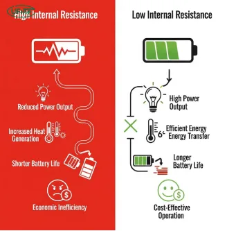
A battery-powered device rarely consumes a perfectly constant current.
Consider a portable robotic device that normally draws 1.5 A but briefly requires 8 A when an actuator starts moving. From an average-power perspective, 1.5 A may appear to be the important number. From the battery’s perspective, however, the 8 A current spike can determine whether the system operates reliably.
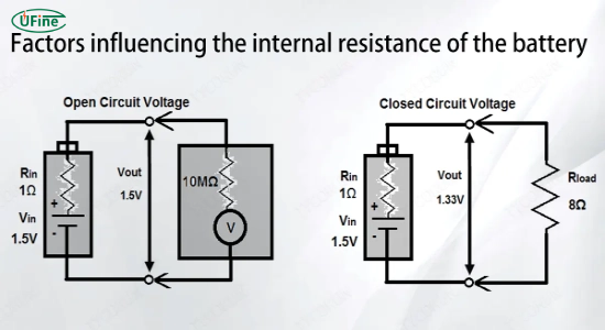
When the load suddenly increases, the battery terminal voltage falls. A simplified relationship is:
Vload = VOCV − I × Rtotal
Here, VOCV is the open-circuit voltage, I is load current, and Rtotal represents the resistance between the battery’s electrochemical source and the device.
Texas Instruments explains that a battery’s terminal voltage falls when current flows because of the I × R voltage drop. Importantly, the response under a transient load is more complicated than a simple resistor because the battery also has electrochemical and capacitive behavior.
This is why a LiPo Battery can appear healthy at low load but cause a system reset when the same device suddenly demands several times more current.
Part 2. The real voltage available to the device
One of the most useful concepts for battery-powered product design is voltage headroom.
Voltage headroom is the difference between the voltage available from the battery under load and the minimum voltage required by the system.
For example, suppose a 1S LiPo Battery has a loaded voltage of 3.35 V while your electronics require at least 3.20 V.
You have only:
3.35 V − 3.20 V = 0.15 V
of usable voltage headroom.
A relatively small additional voltage drop from a connector, cable, MOSFET, or current spike can push the system below its operating limit.
Battery resistance is only part of the equation
The total resistance in a real battery-powered product can include:
- Cell Internal Resistance
- Battery tabs and welds
- Protection MOSFETs
- PCB traces
- Connectors
- Wires
- Fuses or other protection components
Therefore, a better engineering model is:
Rtotal = Rcell + Rprotection + Rconnector + Rwire + RPCB
For a high-current application, ignoring these additional resistances can lead to an overly optimistic battery specification.
Part 3. Why resistance matters more as current increases
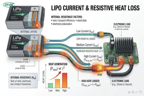
The voltage drop caused by resistance increases linearly with current:
Vdrop = I × R
But the power dissipated as heat increases with the square of current:
Ploss = I² × R
This difference is extremely important.
| Load current | Resistance | Voltage drop | Resistive loss |
|---|---|---|---|
| 2 A | 50 mΩ | 0.10 V | 0.20 W |
| 5 A | 50 mΩ | 0.25 V | 1.25 W |
| 8 A | 50 mΩ | 0.40 V | 3.20 W |
| 10 A | 50 mΩ | 0.50 V | 5.00 W |
The resistance remains exactly the same in this example, but increasing current from 2 A to 10 A increases resistive heat loss by 25 times.
This is why a resistance value that appears insignificant during a low-current test can become a major design limitation in a high-load LiPo Battery application.
Part 4. Internal Resistance can define the practical peak current
A battery’s advertised discharge capability does not automatically mean your device can use that current without a significant voltage drop.
Suppose your system requires a minimum of 3.20 V. At the point where a high-current event occurs, your battery provides 3.60 V.
The available voltage drop is therefore:
3.60 V − 3.20 V = 0.40 V
If the total resistance is 50 mΩ, the theoretical maximum current before reaching the voltage limit is:
Imax = 0.40 V ÷ 0.05 Ω = 8 A
If the total resistance increases to 100 mΩ:
Imax = 0.40 V ÷ 0.10 Ω = 4 A
The battery’s chemical capacity has not changed. The difference comes from the resistance of the power path.
This demonstrates why high-load LiPo Battery selection should not start with mAh alone. The device’s minimum operating voltage and peak current requirement are equally important.
Part 5. Why battery SOC changes high-load behavior
A battery does not behave identically at 100% SOC and near the end of discharge.
As the battery discharges, its open-circuit voltage decreases. At the same time, the voltage drop caused by load current still occurs.
For example:
At higher SOC:
Battery voltage = 3.80 V
Voltage drop = 0.25 V
Loaded voltage = 3.55 V
At lower SOC:
Battery voltage = 3.45 V
Voltage drop = 0.25 V
Loaded voltage = 3.20 V
If the system’s minimum operating voltage is 3.20 V, the second condition leaves virtually no margin.
This explains an important real-world behavior: a device may suddenly shut down under a heavy load even though the battery still contains usable energy.
The problem is not necessarily that the battery is empty. The problem is that the loaded voltage has fallen below the system’s operating threshold.
Part 6. Dynamic loads cannot be represented by one resistance value
A simple Internal Resistance value is useful, but it does not completely describe a battery’s response to a rapidly changing load.
When current changes suddenly, the terminal voltage can respond through several mechanisms. TI’s recent battery-modeling work notes that real battery voltage transients can persist for significant periods, and simple OCV-plus-IR models may not fully capture dynamic behavior.
This matters when your device produces pulses such as:
- Motor startup
- Wireless transmission
- Camera activation
- Speaker output
- Actuator movement
- Processor workload bursts
A 10 A pulse lasting 10 ms is not equivalent to a 10 A load lasting 1 second.
For this reason, battery testing should reproduce the actual load profile, rather than testing only a constant current.
Part 7. Temperature can change the high-load result
Temperature is another variable that should be considered when evaluating a LiPo Battery.
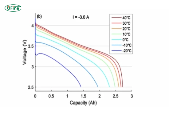
At lower temperatures, electrochemical processes become less favorable and effective resistance can increase. TI documentation also shows that battery resistance can vary significantly with temperature and state of charge.
The result can be particularly noticeable in high-current applications:
Low temperature → higher effective resistance → larger voltage drop → lower voltage headroom
High current can also produce resistive heating:
P = I²R
This creates a feedback relationship in demanding applications. A high current increases heat generation, while the resulting temperature change can alter battery characteristics.
Therefore, a battery specification developed only from room-temperature testing may not accurately predict performance in a cold or thermally constrained product.
Part 8. Cell matching matters in multi-cell LiPo Battery packs
For 2S, 3S, 4S, and larger LiPo Battery packs, individual cell behavior becomes another consideration.
Imagine two cells connected in series:
- Cell A: 30 mΩ
- Cell B: 50 mΩ
- Load: 10 A
The approximate resistive voltage drop is:
Cell A: 10 A × 0.030 Ω = 0.30 V
Cell B: 10 A × 0.050 Ω = 0.50 V
The second cell experiences 0.20 V more voltage drop under the same load.
This difference can become important as the pack approaches a low state of charge. The weaker cell may reach its voltage limit earlier than the other cells, affecting the usable performance of the entire pack.
For this reason, high-power battery packs require attention to cell consistency rather than simply connecting cells with identical nominal capacity.
Part 9. How to specify a LiPo Battery for a high-load device
Instead of starting with “How many mAh do I need?”, start with the device’s electrical load profile.
You should determine:
- Nominal operating voltage
- Minimum system voltage
- Average current
- Peak current
- Peak duration
- Frequency of current spikes
- Operating temperature range
- Required runtime
- Available battery space and weight
- Connector and wiring requirements
Then estimate the allowable resistance using:
Rmax = (Vbattery,min − Vsystem,min) ÷ Ipeak
For example, if the minimum battery voltage available during a peak event is 3.50 V, the system requires 3.20 V, and the peak current is 6 A:
Rmax = (3.50 − 3.20) ÷ 6 = 50 mΩ
That 50 mΩ is effectively a budget for the entire high-current path, not necessarily just the LiPo cell.
1 Designing around resistance instead of simply minimizing it
Lower resistance is generally beneficial for high-load applications, but it should not become the only design objective.
A battery optimized for extremely high current may require different cell construction, dimensions, thermal management, or cost compared with a battery optimized primarily for energy density.
For a wearable device drawing a few hundred milliamps, for example, reducing resistance from one low value to an even lower value may provide little practical benefit.
For a robotic actuator drawing several amps, however, resistance can directly determine whether the actuator receives sufficient voltage during acceleration.
The better approach is to balance:
Capacity + voltage + peak current + Internal Resistance + size + weight + temperature + protection
The “best” LiPo Battery is therefore application-dependent.
2 Practical example: selecting a LiPo Battery for a high-load device
Consider a portable consumer device with the following requirements:
| Parameter | Requirement |
|---|---|
| Battery configuration | 1S LiPo |
| Nominal voltage | 3.7 V |
| Capacity | ≥2,000 mAh |
| Average current | 1.5 A |
| Peak current | 8 A |
| Peak duration | 200 ms |
| Minimum system voltage | 3.20 V |
If the battery can reach 3.60 V immediately before the peak event, the available voltage margin is:
3.60 − 3.20 = 0.40 V
At an 8 A peak load, the maximum theoretical total resistance is:
0.40 ÷ 8 = 50 mΩ
This means the battery specification should target a sufficiently low resistance while also considering the resistance of the connector, protection circuit, wires, and PCB.
If the system is expected to operate at low temperatures or near the end of discharge, additional design margin should be included rather than designing exactly around the 50 mΩ limit.
This approach gives you a much more reliable battery specification than simply requesting a “2,000 mAh high-rate battery.”
Part 10. FAQs
Does a longer battery cable reduce LiPo Battery performance?
It can. Longer or thinner cables generally add resistance to the power path. At high current, even a small increase in resistance can create additional voltage drop and heat, reducing the voltage available to the device.
Can adding cells in parallel improve high-load performance?
Adding cells in parallel can reduce the effective resistance of the cell group and distribute the load current among multiple cells. However, the pack still needs appropriate cell matching, connections, protection, and thermal management.
Why is voltage measured at the battery terminals different from voltage measured at the device?
The difference can come from resistance in wires, connectors, protection circuits, PCB traces, and other components between the battery and the device. Under high current, these voltage differences become more noticeable.
Does battery size affect Internal Resistance?
Battery size and construction can influence resistance, but physical size alone does not determine Internal Resistance. Electrode design, materials, current-collection structure, cell construction, and intended discharge performance all contribute.
How does battery aging affect high-load performance?
As a LiPo Battery ages, its resistance can increase. Under the same load current, this can produce greater voltage drop and heat generation, reducing the available voltage and potentially causing earlier system shutdown.
Should LiPo Battery testing use the actual device load?
For high-load products, testing with the actual or a representative load profile is strongly recommended. A constant-current test may not reproduce the short, repeated current spikes that occur during real device operation.
Related Tags:

More Articles

Buck vs. Boost vs. Buck-Boost Converter: Which Is Best for Battery?
Not sure which converter your battery-powered device needs? Compare Buck, Boost, and Buck-Boost designs and discover what affects voltage stability and runtime.
How to Match 18650 Cells for a Reliable Battery Pack?
Building an 18650 battery pack? Learn how to compare cell capacity, voltage, and internal resistance to avoid mismatches and improve reliability.
Why Do 18650 Battery Packs Get Hot During Discharge?
Is your 18650 battery pack overheating under load? Learn what causes excess heat, how to spot dangerous symptoms, and what to do next.
18650 Battery BMS: How to Get the Specs Right
Learn how to choose a BMS for an 18650 battery pack. Compare voltage, current ratings, protection features, and balancing before you buy.
Why Does My Ring Camera Battery Drain So Fast or Stop Charging?
Is your Ring camera battery draining fast or not charging? Discover common causes, practical fixes, and when to replace the battery.