- Key takeaways
- Part 1. How to plan a battery wire path before assembly
- Part 2. How to choose battery wires for a compact enclosure
- Part 3. How to route battery wires safely around tight corners
- Part 4. How to secure battery wires without damaging them
- Part 5. How to prevent electrical and thermal problems
- Part 6. Common battery wire routing mistakes
- Part 7. How to inspect and test battery wire routing
- Part 8. How custom LiPo battery design simplifies wire routing
- Part 9. FAQs
NASA’s active workmanship standard for electrical interconnections, NASA-STD-8739.4, addresses cable and harness assembly practices, including bend radius, strain relief, and protection against mechanical damage. Although developed for NASA applications rather than ordinary consumer electronics, it provides a useful engineering reference for understanding reliable wire routing.
For compact battery-powered products, the best approach is to plan the wire path during enclosure design, select suitable battery wires, protect them from mechanical stress, and validate the complete assembly before production.
Key takeaways
- Plan battery wire routing before finalizing the enclosure layout.
- Select wire gauge according to current, wire length, voltage drop, and temperature limits.
- Follow the wire manufacturer’s minimum bend-radius requirements.
- Protect wires from sharp edges, moving parts, screws, and enclosure pinch points.
- Use suitable retainers and strain relief without crushing the insulation.
- Test wire routing under realistic electrical, thermal, and mechanical conditions.
Part 1. How to plan a battery wire path before assembly
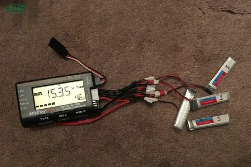
Battery wires carry power between the battery and the device’s circuit board or power input. In a compact enclosure, their position affects electrical performance, mechanical reliability, and ease of assembly.
A wire that is too thin or unnecessarily long can increase resistance and voltage drop. A wire trapped beneath a cover can develop damaged insulation, while a connector under constant tension may become loose over time.
Routing also affects maintenance. If the battery needs replacement, wires should not obstruct screws, prevent the enclosure from closing, or require excessive force during disassembly.
The goal is to create a short, protected, and serviceable path without compromising the battery, connectors, or surrounding components.
Plan the route before fixing the battery position and finalizing the enclosure. Identify the battery leads, PCB connection points, connector orientation, mounting posts, screws, and enclosure seams.
A practical planning process includes:
- Mark the battery’s location and the destination of each wire.
- Identify possible pinch points, sharp edges, moving parts, and heat sources.
- Reserve enough space for the wires and their natural bends.
- Check connector insertion and removal clearance.
- Account for manufacturing tolerances so the wires are not compressed when the enclosure closes.
Avoid choosing the shortest route automatically. A slightly longer path that avoids sharp corners and provides strain relief may be more reliable than a tightly stretched wire.
Part 2. How to choose battery wires for a compact enclosure
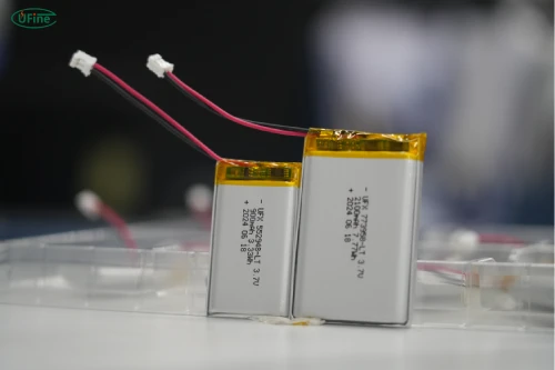
The correct battery wire depends on current, length, insulation, temperature, and mechanical conditions. Thin wires save space, but choosing them only for their small diameter can cause excessive voltage drop or heating.
| Selection factor | What to consider |
|---|---|
| Wire gauge | Current capacity, temperature rise, and voltage drop |
| Wire length | Resistance, flexibility, and available space |
| Insulation | Temperature rating, abrasion resistance, and flexibility |
| Conductor type | Stranded wire for flexible connections where appropriate |
| Connector | Current rating, contact size, polarity, and clearance |
Wire resistance increases with length and decreases as conductor cross-sectional area increases. As a result, a long, thin wire may lose more voltage than a short, thicker wire carrying the same current.
For a basic estimate:
Voltage drop (V) = Current (A) × Total circuit resistance (Ω)
For a two-wire DC circuit, include the resistance of both the positive and negative conductors, as well as relevant connector and contact resistance.
Insulation also matters. Select materials appropriate for the device’s operating temperature, flexibility requirements, and expected exposure to friction. Do not assume that all small-gauge wires have the same insulation properties.
Part 3. How to route battery wires safely around tight corners
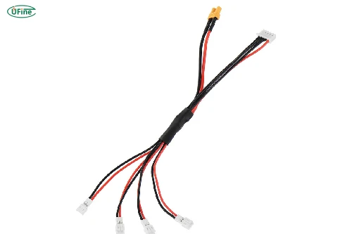
Tight enclosures often force wires to turn around batteries, circuit boards, and structural features. However, sharp bends can stress conductors and insulation, especially near solder joints, battery tabs, and connectors.
Follow the minimum bend radius specified by the wire or cable manufacturer. The appropriate radius depends on conductor construction, insulation, and whether you are bending an individual wire or a complete harness. There is no single minimum bend radius suitable for every battery wire.
When routing around corners:
- Use smooth curves instead of sharp folds.
- Avoid repeatedly bending the same section during assembly.
- Keep bends away from solder joints and connector exits where possible.
- Protect wires from exposed PCB edges and metal components.
- Ensure the enclosure does not force the wire into a tighter bend when closed.
Never fold a LiPo pouch battery to create extra space for its wires. The battery itself must remain within its specified mechanical limits.
Part 4. How to secure battery wires without damaging them
Once the route is established, secure the wires so they cannot shift into dangerous positions during normal use, vibration, or assembly.
Suitable methods include molded wire channels, clips, retaining features, and appropriately selected adhesive-backed holders. Cable ties may be useful in some designs, but excessive tightening can deform insulation or create concentrated mechanical stress.
Pay particular attention to strain relief near battery terminals and connectors. The wire should not pull directly on a solder joint or battery tab when the enclosure is opened or the device is moved.
Do not place rigid retainers where they could press against a soft LiPo pouch. Adhesives and other retaining materials should also be compatible with the insulation and enclosure materials.
Part 5. How to prevent electrical and thermal problems
Keep battery wires away from sharp conductive surfaces and exposed contacts. Positive and negative conductors must remain properly insulated, and their routing should not allow screws or metal parts to bridge them.
Consider heat from processors, power converters, motors, and charging circuits. Verify that the wire insulation, connectors, and battery can tolerate the actual operating temperatures.
For electrically sensitive devices, consider electromagnetic interference as well. High-current battery leads routed close to antennas or sensitive signal circuits may affect performance, depending on the current waveform and circuit design. Follow the product’s grounding, separation, and EMC requirements rather than assuming that physical separation alone will solve every issue.
A battery protection circuit is not a substitute for correct wire sizing, insulation, and mechanical protection. Protection circuitry may not prevent every short circuit or localized heating event.
Part 6. Common battery wire routing mistakes
Several mistakes can undermine an otherwise good design:
- Choosing wire gauge based only on space: Current capacity and voltage drop must also meet the design requirements.
- Making wires too short: Tension can develop at terminals and connectors.
- Leaving excessive slack: Loose wire can become trapped under covers or screws.
- Ignoring sharp edges: Repeated friction can damage insulation.
- Overtightening retainers: Excessive pressure can damage the wire.
- Skipping enclosure-closure checks: A route that looks safe when open may be pinched when assembled.
The most reliable design is one that remains safe after the device is fully assembled, not just while the internal components are exposed.
Part 7. How to inspect and test battery wire routing
Before approving a design, check both electrical performance and physical routing.
| Test | What to verify |
|---|---|
| Visual inspection | No pinching, exposed conductors, or damaged insulation |
| Assembly check | Wires remain clear of seams, screws, and clips |
| Electrical test | Acceptable voltage drop under expected loads |
| Mechanical test | No harmful movement or abrasion during vibration or impact |
| Thermal test | Wire and connector temperatures remain within rated limits |
Repeat inspections after relevant mechanical tests. Look for marks on insulation, loose retainers, connector movement, and changes in the wire path.
Testing should reflect the actual product and its intended environment. A design that works on a workbench may behave differently after repeated assembly, vibration, or drops.
Part 8. How custom LiPo battery design simplifies wire routing
Battery dimensions and lead configuration directly affect enclosure layout. A battery with the right capacity may still be difficult to install if its wires exit in the wrong direction or its connector occupies too much space.
Custom LiPo battery design can help coordinate:
- Battery dimensions and available enclosure volume.
- Wire exit direction and lead length.
- Connector type, polarity, and position.
- Current requirements and conductor sizing.
- Assembly access and mechanical protection.
Ufine Battery provides custom lithium battery solutions for products with specific size and electrical requirements. When requesting a custom battery, share the enclosure dimensions, battery mounting location, current requirements, connector specifications, and preferred wire exit direction.
Planning these details early can reduce excess wiring, simplify assembly, and help prevent interference between the battery and other components.
Part 9. FAQs
1. Can battery wires be bundled together inside a small device?
Yes, when the wire insulation, current capacity, temperature limits, and routing conditions are suitable. Bundling can simplify assembly, but tightly packed wires may reduce heat dissipation and make inspection or servicing more difficult.
2. Should battery wires be soldered directly to a PCB?
Direct soldering may be appropriate for some designs, but it requires suitable pads, correct soldering processes, and mechanical strain relief. A connector may be preferable when the battery needs to be replaced or the product requires easier assembly and servicing.
3. Is thicker battery wire always better?
No. Thicker wire generally has lower resistance, but it occupies more space and may be less flexible. Choose a conductor that meets current, voltage-drop, temperature, and mechanical requirements without making the enclosure difficult to assemble.
4. How can battery wires be protected from vibration?
Use suitable retainers, strain relief, and abrasion protection. Avoid unsupported wire spans and ensure connectors or solder joints do not bear the full mechanical load. Verify the design through testing that reflects the product’s intended use.
5. What information should be included in a battery wire routing drawing?
Include the wire length, gauge, insulation specification, connector type, polarity, exit direction, routing path, retention points, and any applicable bend-radius or clearance requirements. These details help ensure the design can be reproduced consistently.
Related Tags:

More Articles

How to Audit a Battery Manufacturer Before You Buy
Not sure if a battery supplier is reliable? Learn what to inspect, which records to request, and how to spot risks before placing an order.
How to Match Battery Discharge Current to Motor Startup Demand
Does your motor struggle to start? Learn how to calculate startup current, prevent voltage drop, and choose a battery that delivers reliable power.
Battery Gets Hot While Fast Charging? Here’s What to Do
Does your LiPo battery get hot during fast charging? Discover the main causes, warning signs, and practical ways to reduce overheating.
Dead Battery or Device Failure? How to Find the Cause
Think your device is broken? Learn how to tell if the problem comes from battery aging or hardware failure before replacing your electronics.
Why iPhone Duo Uses Two Batteries: The Engineering Behind Foldable Phone Power
Why do foldable phones need two batteries? Explore the engineering challenges behind iPhone Duo’s dual-battery architecture and future battery trends.