- Part 1. What does 18650 3S2P mean?
- Part 2. What components do you need to build a 3S2P battery pack?
- Part 3. How to choose the right 18650 cells
- Part 4. How to build an 18650 3S2P battery pack
- Part 5. How to wire a 3S2P battery pack correctly
- Part 6. How to choose the right connectors and connecting wires
- Part 7. How to test your 3S2P battery pack after assembly
- Part 8. Common problems when building a 3S2P battery pack
- FAQs
Among the many available battery configurations, the 18650 3S2P battery pack is a practical option when an application requires a balance of voltage, capacity, and compact size. But how do you build one? What components do you need, and how should you choose the right cells, BMS, connectors, and wires?
In this guide, we’ll walk through the essential considerations for designing an 18650 3S2P battery pack, from understanding its configuration to testing the finished assembly.
Key takeaways
-
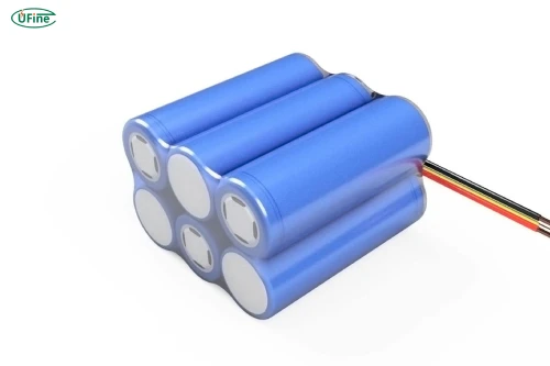
An 18650 3S2P battery pack uses six cells arranged in three series groups, with two cells connected in parallel in each group.
-
A typical 3S lithium-ion pack has a nominal voltage of 10.8V or 11.1V and a fully charged voltage of 12.6V.
-
Cell capacity doubles through parallel connections, while series connections increase voltage.
-
A compatible 3S BMS helps manage overcharge, over-discharge, overcurrent, and cell balancing.
-
Connector and wire selection should match the pack’s current requirements, operating environment, and device interface.
-
Professional assembly, insulation, and electrical testing are essential for battery pack safety.
Part 1. What does 18650 3S2P mean?
Before building a battery pack, you need to understand its configuration.
The term 18650 describes a cylindrical lithium-ion cell measuring approximately 18mm in diameter and 65mm in length. The final zero indicates its cylindrical shape.
The numbers and letters in 3S2P describe how the cells are electrically connected:
-
3S (Three in Series): Three cell groups are connected in series to increase the overall voltage.
-
2P (Two in Parallel): Two cells are connected in parallel within each group to increase capacity and current capability.
This means an 18650 3S2P battery pack contains six individual cells in total.
| Specification | Typical value |
|---|---|
| Number of cells | 6 |
| Configuration | 3S2P |
| Nominal cell voltage | 3.6V or 3.7V |
| Nominal pack voltage | 10.8V or 11.1V |
| Fully charged voltage | 12.6V |
| Capacity | 2 × individual cell capacity |
| Total energy | Pack voltage × pack capacity |
For example, if you use six 18650 cells rated at 2,500mAh each, the resulting pack has a nominal capacity of 5,000mAh.
With a nominal voltage of 11.1V, its approximate energy is:
11.1V × 5Ah = 55.5Wh.
Understanding these values helps you determine whether a 3S2P configuration meets your device’s power requirements.
Part 2. What components do you need to build a 3S2P battery pack?
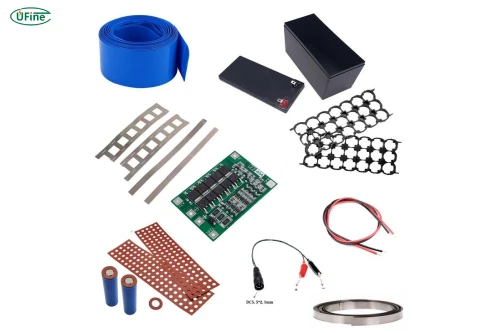
A reliable battery pack requires more than six lithium-ion cells. Each component plays a role in electrical performance, mechanical stability, or protection.
1. Six compatible 18650 cells
Choose rechargeable lithium-ion cells with matching chemistry, voltage, capacity, discharge characteristics, and similar internal resistance. Using cells from the same model and production batch is preferable.
2. A compatible 3S BMS
A Battery Management System monitors the battery pack and provides essential protection functions, including overcharge, over-discharge, overcurrent, and short-circuit protection. A balancing function helps maintain similar voltage levels between series groups.
3. Nickel strips and cell holders
Nickel strips are commonly used as electrical interconnections in professionally assembled packs. Their material, thickness, and dimensions must be selected according to the required current and thermal performance.
4. Insulation and protective materials
Insulating rings, fish paper, heat-resistant barriers, and an appropriate outer enclosure help prevent accidental short circuits and physical damage.
5. Connectors and connecting wires
These components connect the battery pack to the target device or charging system. Their current ratings, wire sizes, and mechanical compatibility must match the application.
6. A compatible charger
A conventional three-series lithium-ion battery pack requires a dedicated 12.6V CC/CV charging system, together with the appropriate charging current and protection arrangements.
Part 3. How to choose the right 18650 cells
Cell selection directly affects battery performance, runtime, and service life.
First, consider the required capacity. Higher-capacity cells can provide more energy, but they may have different discharge characteristics. Don’t choose cells based on mAh alone.
Next, check the continuous discharge current. If your device requires a high operating current, select cells designed to support that load without excessive heating or voltage drop.
Internal resistance is another important factor. Cells with significantly different internal resistance may experience uneven current distribution and heating when connected in parallel.
Finally, avoid mixing old and new cells or combining different cell models without proper engineering validation. A battery pack performs more consistently when all six cells have compatible electrical characteristics.
Part 4. How to build an 18650 3S2P battery pack
Building a lithium-ion battery pack involves electrical and fire hazards. The following steps describe the design and assembly workflow; actual cell interconnection and BMS installation should be performed by trained battery technicians using appropriate equipment.
Step 1: Determine the electrical requirements
Calculate the required nominal voltage, capacity, energy, and maximum continuous and peak discharge current. Confirm that the 3S2P configuration is suitable for the target device.
Step 2: Select and inspect the six cells
Check cell specifications, voltage, internal resistance, physical condition, and compatibility. Reject damaged, swollen, leaking, or otherwise questionable cells.
Step 3: Design the three parallel groups
Each group contains two matched 18650 cells connected in parallel. There are three such groups in the complete battery pack.
Step 4: Connect the three groups in series
The three parallel groups are connected in series to achieve the required pack voltage. This connection should follow a verified electrical design rather than an improvised wiring arrangement.
Step 5: Install the 3S BMS
A compatible BMS is integrated into the battery system to monitor the three series groups and provide the required protection and balancing functions. Its wiring must follow the manufacturer’s exact connection diagram.
Step 6: Add insulation and mechanical protection
Protect exposed electrical connections and prevent cells from moving or contacting conductive materials. Add suitable insulation and an enclosure designed for the operating environment.
Step 7: Install the output connections
Fit the specified power connector, output wires, and any required charging interface. Ensure the connection is mechanically secure and electrically compatible with the device.
Part 5. How to wire a 3S2P battery pack correctly
The key to a 3S2P configuration is understanding the difference between series and parallel connections.
In each parallel group, two cells share the same electrical voltage, while their capacities and current capabilities combine. The three resulting groups are then connected in series.
The BMS typically uses several monitoring connections:
-
B-: Main battery negative.
-
B1: First series-group voltage monitoring point.
-
B2: Second series-group voltage monitoring point.
-
B+: Main battery positive.
These connections allow the BMS to monitor the individual series groups.
Incorrect BMS wiring can damage the protection circuit or create dangerous operating conditions. Never assume that different BMS models share the same terminal layout. Always follow the manufacturer’s wiring diagram and have the completed assembly independently checked before use.
Part 6. How to choose the right connectors and connecting wires
Connectors and wires are sometimes overlooked during battery design, but they directly affect power delivery, heat generation, and reliability.
Choosing the right battery connector
Start with the maximum continuous current and peak current required by your device. The connector must have an adequate current rating under the actual operating conditions.
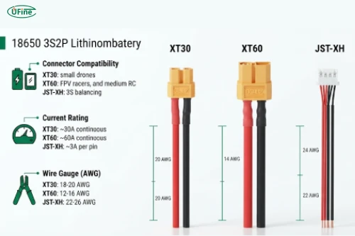
Common connector options include:
-
XT30: Often used in compact battery applications with relatively modest current requirements.
-
XT60: Common in applications requiring higher current handling.
-
JST connectors: Available in various configurations and commonly used for low-current connections, signal wiring, and certain compact devices.
These are examples rather than universal recommendations. Always check the manufacturer’s current rating, contact specifications, temperature limits, and compatibility before selecting a connector.
Also consider connector size, locking structure, contact resistance, polarity, and the available installation space.
Choosing the correct connecting wire
Wire selection depends on several factors:
-
Maximum continuous and peak current.
-
Wire length and acceptable voltage drop.
-
Insulation temperature rating.
-
Installation environment and flexibility requirements.
-
Mechanical protection and routing space.
A wire that is too thin can produce excessive resistance and heat. However, choosing an unnecessarily thick wire can make installation difficult and increase the space required inside the device.
For a reliable battery system, calculate the appropriate wire size based on the actual load and installation conditions rather than choosing an AWG size simply because it is commonly used in another battery pack.
Part 7. How to test your 3S2P battery pack after assembly
Before putting a new battery pack into service, it needs to undergo electrical and functional testing.
Start by checking the total pack voltage and comparing the three series-group voltages. Significant differences may indicate cell mismatch, incorrect connections, or a problem with the assembly.
Next, verify output polarity and connector continuity. An incorrect positive or negative connection can damage the connected electronic device.
The BMS should also be checked to confirm that its protection and balancing functions operate according to the manufacturer’s specifications.
Finally, conduct controlled load testing to evaluate voltage stability, current delivery, and temperature. Watch for unusual heating, abnormal voltage drops, or unexpected protection cutoffs.
If the pack becomes unusually hot, swells, smells abnormal, or shows signs of damage, stop testing and isolate it using appropriate safety procedures.
Part 8. Common problems when building a 3S2P battery pack
Even when the configuration is correct on paper, several problems can affect the finished battery pack.
Uneven cell voltage: Differences in cell condition or capacity can lead to inconsistent voltage levels between groups. Proper cell matching and BMS balancing are important.
Incorrect BMS wiring: Connecting monitoring wires to the wrong terminals can damage the BMS and compromise protection.
Unexpected voltage drop: High connection resistance, unsuitable wires, or cells with insufficient discharge capability can cause voltage drops under load.
Overheating: Excessive current, poor electrical connections, inadequate insulation design, or unsuitable cells can generate dangerous heat.
Insufficient runtime: Actual runtime depends on usable battery energy, device power consumption, discharge conditions, and conversion efficiency.
Understanding these problems early helps you design a more reliable battery system and avoid costly failures.
FAQs
1. What is the voltage of an 18650 3S2P battery pack?
A typical 3S lithium-ion pack has a nominal voltage of 10.8V or 11.1V and a maximum charging voltage of 12.6V.
2. What is the capacity of a 3S2P battery pack?
Its capacity is twice the capacity of one individual cell. For example, six 2,500mAh cells produce a nominal 5,000mAh pack.
3. Can I use different-capacity 18650 cells in a 3S2P pack?
Using cells with different capacities is generally not recommended. Capacity and electrical characteristics should be matched to reduce uneven loading and premature aging.
4. What charger should I use for a 3S2P battery pack?
Use a compatible 12.6V CC/CV lithium-ion charger. Its charging current must also meet the battery manufacturer’s specifications.
5. Can I use a 3S2P battery pack for a 12V device?
Potentially, yes. However, check the device’s actual input voltage range, current requirements, and tolerance for voltage changes throughout the battery’s discharge cycle.
Related Tags:

More Articles
How to Build a 7.4V 18650 Battery Pack: Full Guide
Building a 7.4V 18650 battery pack? Discover the right cells, 2S configuration, BMS, wiring, and common mistakes to avoid.
Solar Battery Bank: How Many Batteries Are Enough?
Find out how many batteries your solar system needs. Learn how to calculate battery capacity, compare battery types, and avoid costly sizing mistakes.
Swollen Laptop Battery? Don’t Ignore These Signs
Is your laptop case bulging? Find out why lithium batteries swell, what risks you should know, and how to handle a swollen battery safely.
200 Amp Lithium Battery: Better Than Lead-Acid?
Is a 200Ah lithium battery worth the extra cost? Compare runtime, lifespan, usable power, and long-term savings before you buy.
Where to Find Reliable LiPo Battery Suppliers for OEM Projects
Looking for LiPo battery suppliers? Discover where to find reliable manufacturers and how to avoid costly sourcing mistakes.