- Part 1. Start with the battery envelope, not just its rated dimensions
- Part 2. Clearance between a LiPo battery and PCB
- Part 3. Electrical insulation: what the battery packaging does and does not protect
- Part 4. Battery placement relative to heat-generating components
- Part 5. PCB layout and battery electrical performance
- Part 6. Connector and wire exit direction can change the PCB layout
- Part 7. Mechanical retention: prevent movement without compressing the cell
- Part 8. Design for manufacturing and assembly
- Part 9. When standard battery dimensions become a design constraint
- Part 10. A practical battery–PCB integration review
- Part 11. FAQs
A LiPo battery and PCB may occupy the same small enclosure, but they should not simply be treated as two components that happen to fit together. Battery placement affects mechanical stress, insulation, thermal conditions, current delivery, wiring, and assembly reliability.
The key question is not simply “Can a LiPo battery touch a PCB?” Instead, you should ask whether the battery has enough mechanical clearance, adequate electrical insulation, a suitable thermal environment, and a reliable retention method throughout the product’s operating life.
Key takeaways
- Design around the battery’s full mechanical envelope, not only its nominal dimensions.
- Define a battery keep-out zone around the cell, tabs, wires, connector, and protection circuit.
- PCB components, solder joints, edges, and metal parts can create localized pressure or abrasion against a LiPo pouch cell.
- Additional insulation can reduce electrical risk, but it should not be used to compensate for poor mechanical design.
- Keep the battery away from major PCB heat sources whenever the product’s thermal architecture allows it.
- For high-current products, PCB traces, connectors, wires, and battery internal resistance all contribute to voltage drop.
- Mechanical retention should prevent battery movement without unnecessarily compressing the pouch cell.
- If a standard battery cannot fit the product architecture efficiently, a custom LiPo battery can often solve the problem at the battery-design stage.
Part 1. Start with the battery envelope, not just its rated dimensions
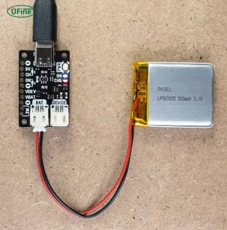
A battery datasheet might specify a size such as 5 × 30 × 50 mm. It is tempting to create a matching cavity in the CAD model and move on.
In a real product, that is rarely enough.
The nominal battery dimensions do not necessarily represent the complete space required for integration. You may also need to account for pouch thickness variation, protective tape, tabs, wires, connectors, a PCM or protection circuit, and manufacturing tolerances.
For example, a battery that appears to fit beneath a PCB may become difficult to assemble once the connector and wire exit are included.
A better approach is to define a complete battery design envelope before finalizing the PCB and enclosure.
| Battery area | What to consider during PCB design |
|---|---|
| Cell body | Thickness variation, compression, surface contact |
| Tabs | Tab direction, insulation, bending and mechanical stress |
| Wire exit | Bend radius, pinch points, routing space |
| Connector | Connector height, mating direction, service access |
| Protection circuit | PCB/component height and exposed conductive areas |
| Battery edges | Abrasion, enclosure contact, assembly tolerance |
This envelope should then be converted into a practical battery keep-out zone in the mechanical design.
Why stack-up analysis matters
Consider a simple product stack:
PCB → components → insulation/barrier → LiPo battery → enclosure
Every layer has its own tolerance. A design that barely fits in nominal CAD dimensions may become an interference problem after manufacturing variation is introduced.
This is why battery- PCB integration should be reviewed using worst-case stack-up conditions rather than assuming that every component will remain exactly where it appears in the CAD model.
Part 2. Clearance between a LiPo battery and PCB
There is no single universal LiPo battery PCB clearance that works for every product.
The required clearance depends on the cell construction, PCB components, enclosure, assembly method, vibration environment, and whether the battery is supported by another structure.
Contact is not the same as pressure
A common question is whether a LiPo battery can physically contact a PCB.
The more useful question is whether the PCB can apply localized or sustained pressure to the battery.
A smooth, controlled surface is very different from a solder joint, component lead, sharp PCB edge, or protruding connector pressing against a pouch cell.
Mechanical damage, indentation, vibration, and other forms of abuse are recognized contributors to lithium-ion battery failure, so mechanical integration should be treated as part of the battery safety design rather than as a cosmetic packaging issue.
You should therefore pay particular attention to:
- Tall components underneath or beside the cell
- Exposed solder joints
- Sharp PCB edges
- Metal shields
- Connector pins
- Screws or brackets
- Enclosure ribs
- Areas where the PCB can flex
The objective is not necessarily to create a large empty gap everywhere. It is to prevent uncontrolled contact, concentrated pressure, and movement during the product’s lifetime.
Part 3. Electrical insulation: what the battery packaging does and does not protect
The outer pouch film of a LiPo battery provides electrical insulation and environmental protection, but it should not be considered structural armor.
A PCB can contain many features capable of damaging or penetrating that insulation during assembly or operation.
For example, imagine a battery installed directly beneath a PCB. During assembly, the board may slide across the battery surface. Later, vibration may cause repeated micro-movement. A sharp solder joint or PCB edge could gradually abrade the pouch film.
This is very different from a battery simply resting near a smooth insulated surface.
When additional insulation is useful
Depending on the mechanical architecture, designers may use:
- Insulating film
- Protective tape
- Foam barriers
- Non-conductive separators
- Protective covers around exposed conductors
However, additional insulation should be considered a secondary protection layer.
If the battery is being squeezed between the PCB and enclosure, adding another piece of tape does not solve the underlying mechanical problem.
A robust design combines electrical isolation with controlled mechanical clearance.
Part 4. Battery placement relative to heat-generating components
PCB layout is also a thermal problem when a LiPo battery is located inside the same enclosure.
Not every PCB component produces significant heat, but some components can become important heat sources under continuous load:
- DC-DC converters
- MOSFETs
- Charging ICs
- Motor drivers
- Power amplifiers
- Processors operating at sustained load
- High-current switching components
Placing the battery directly against a major heat source can increase the cell’s operating temperature.
This matters because battery performance and aging are influenced by temperature. Charging and discharging under unfavorable thermal conditions can also increase battery stress.
Instead of treating the PCB as one uniform heat source, map the actual thermal zones.
Ask:
Where is heat generated?
How does that heat leave the PCB?
Which part of the battery is closest to that thermal path?
For example, moving a battery only a few millimeters away from a hot power converter may have more practical value than increasing the overall clearance around a cool section of the PCB.
The goal is not simply to maximize distance. It is to prevent the battery from becoming part of an undesirable thermal path.
Part 5. PCB layout and battery electrical performance
Physical placement also affects electrical performance.
The current path may look simple:
Battery → wire → connector → PCB → load
But every section introduces resistance.
At high load current, even a relatively small resistance can produce meaningful voltage drop:
Vdrop = I × R
The total resistance can include:
- Battery internal resistance
- Wire resistance
- Connector resistance
- PCB trace resistance
- Protection circuit resistance
This becomes particularly important for products with motors, actuators, wireless transmitters, processors, or other dynamic loads.
A battery may have the correct nominal voltage and capacity but still produce poor system performance if the current path is too resistive.
TI’s battery-management reference designs, for example, explicitly incorporate battery monitoring, protection, charging, and current-related system considerations rather than treating the cell as an isolated component.
For high-current designs, battery placement and PCB layout should therefore be reviewed together.
Part 6. Connector and wire exit direction can change the PCB layout
Two LiPo batteries can have exactly the same voltage, capacity, and cell dimensions but still have very different integration requirements.
The reason may simply be the wire and connector configuration.
A connector exiting from the short side may work perfectly in one enclosure but create a serious interference problem in another. A vertical connector can require additional height, while a side-exit connector may allow a thinner product.
The wire exit also needs a controlled routing path.
Avoid situations where the wire is:
- sharply bent immediately after leaving the battery
- trapped between the PCB and enclosure
- pressed against a sharp edge
- repeatedly flexed by a moving component
- pulled directly by the connector
This is particularly important in compact products where the battery and PCB have very little routing space.
Part 7. Mechanical retention: prevent movement without compressing the cell
A battery should not be allowed to move freely inside a product.
Movement can cause abrasion, wire fatigue, connector stress, and repeated impact against the enclosure or PCB.
But the opposite approach—clamping the battery tightly—can also create problems.
The better strategy is controlled retention.
A battery pocket can use suitable support surfaces, cushioning materials, or retention features to keep the cell in position while avoiding unnecessary localized compression.
Think of the design as solving two opposite problems:
Too little retention → battery movement
Too much retention → battery compression
The ideal design keeps the battery stable while accommodating normal manufacturing tolerance and environmental movement.
Part 8. Design for manufacturing and assembly
A battery may fit perfectly in a CAD model and still be difficult to manufacture.
Consider the actual assembly sequence.
If the battery is installed first, can the PCB be positioned without scraping the pouch?
If the PCB is installed first, can the battery connector still be reached?
Can an operator accidentally trap the battery wire beneath the board?
Can the enclosure press the battery against the PCB after final assembly?
These questions are especially important for products with thin housings and tightly packed internal components.
A good battery PCB design therefore considers not only the final assembled product but also how the battery gets there.
Part 9. When standard battery dimensions become a design constraint
Sometimes the problem is not poor PCB design. The standard battery itself simply does not match the product architecture.
This commonly happens when a device has:
- An irregular internal cavity
- Very limited thickness
- A connector that must exit from a specific direction
- A PCB occupying most of the available area
- A curved or unusual enclosure
- A requirement to maximize battery capacity within a fixed volume
In these situations, forcing a standard battery into the design can waste internal space or create unnecessary mechanical compromises.
A custom LiPo battery can instead be designed around the product’s actual requirements, including dimensions, thickness, capacity, wire length, connector, tab configuration, and protection circuit.
This changes the design process from:
“Which standard battery can fit here?”
to:
“What battery geometry works best with the whole product?”
For compact consumer electronics, that difference can be significant.
Get the right LiPo battery for your PCB layout, space constraints, power requirements, and application.
TALK TO A BATTERY EXPERTPart 10. A practical battery–PCB integration review
Before freezing the PCB and enclosure, review the battery integration systematically.
| Design review | Key question |
|---|---|
| Battery envelope | Have you included the cell, tabs, wires, connector and protection circuit? |
| Keep-out zone | Could any PCB feature create pressure or abrasion? |
| Insulation | Are exposed conductive or sharp features properly isolated? |
| Thermal | Is the battery close to a significant heat source? |
| Current path | Is resistance in the battery-to-load path acceptable? |
| Wiring | Are wire routing and connector orientation controlled? |
| Retention | Can the battery move without being excessively compressed? |
| Assembly | Can the battery and PCB be assembled without damaging either one? |
| Tolerance | Does the design still work under realistic dimensional variation? |
| Validation | Has the assembled product been tested under real operating conditions? |
This review is much more useful than simply checking whether the battery outline overlaps the PCB outline in CAD.
Part 11. FAQs
1. Does PCB thickness affect LiPo battery placement?
PCB thickness itself is usually not the main concern. The more important factor is the total stack-up height, including PCB components, connectors, insulation, battery thickness, and enclosure tolerances. A thin PCB can still create interference if tall components are located near the battery.
2. Should the battery and PCB have separate mounting structures?
Not necessarily. Some products use a shared mechanical structure, while others give the battery and PCB independent mounting features. What matters is that PCB movement, enclosure deformation, and assembly forces do not transfer excessive stress to the battery.
3. Can PCB flexing damage a LiPo battery?
It can. If a flexible or poorly supported PCB repeatedly moves against the battery, it may create friction, localized pressure, or abrasion. This is especially worth checking in products exposed to vibration, impact, or repeated mechanical loading.
4. How does vibration affect LiPo battery and PCB integration?
Vibration can turn seemingly harmless contact into a long-term reliability problem. Repeated movement between the battery, PCB, wires, connectors, or enclosure can cause abrasion, connector fatigue, and mechanical stress. Retention and cushioning should therefore be evaluated for the actual operating environment.
5. Can a PCB connector be mounted close to a LiPo battery?
Yes, but the connector’s height, orientation, mating motion, exposed contacts, and cable routing need to be considered. A connector that fits in the PCB layout may still interfere with the battery or enclosure after assembly.
Related Tags:

More Articles

Battery Calibration: Why Is Your Battery % Wrong?
Is your battery percentage inaccurate? Learn how battery calibration works, when you need it, and how to fix unexpected battery drops.
Battery Calibration Guide: Fix SOC Errors in Lithium Systems
SOC accuracy problems can reduce device reliability. Learn how battery calibration, BMS, and fuel gauge optimization improve lithium battery performance.
How Internal Resistance Limits LiPo Battery Performance
Your LiPo Battery may have enough capacity but still fail under load. Discover how Internal Resistance causes voltage sag, heat, and power loss.
What Engineers Can Learn From a Discharge Curve for LithiumBattery?
What can a discharge curve for lithium ion battery tell engineers? Learn how voltage, C-rate, temperature, and capacity affect real-world performance.