- Part 1. What you need before connecting a 4S LiFePO4 BMS
- Part 2. Understand the 4S LiFePO4 BMS wiring terminals
- Part 3. Understand the 4S LiFePO4 BMS wiring diagram
- Part 4. How to connect a 4S LiFePO4 BMS step by step
- Part 5. How to check the 4S LiFePO4 BMS connections
- Part 6. Common 4S LiFePO4 BMS wiring mistakes
- FAQs
If you’re building a 12V LiFePO4 battery pack using four cells connected in series, you’ll need a compatible 4S Battery Management System (BMS). But knowing where to connect B-, B1, B2, B3, and B+ is essential. A single wiring mistake can damage the protection board or create a potentially dangerous battery fault.
In this guide, you’ll learn how a 4S LiFePO4 BMS works, what each terminal does, how to connect the balance wires, and how to check your connections before using the battery pack.
Key takeaways
-
A 4S LiFePO4 battery pack consists of four cells connected in series, with a nominal voltage of 12.8V.
-
A typical 4S LiFePO4 battery reaches 14.6V when fully charged, based on a 3.65V-per-cell charging voltage.
-
B-, B1, B2, B3, and B+ are the main battery and cell-voltage sensing connection points.
-
The balance wires must follow the correct electrical sequence to ensure accurate cell monitoring.
-
Common-port and separate-port BMS designs have different charging and discharging connections.
-
Always verify cell voltages, polarity, and wiring against the manufacturer’s instructions before connecting the BMS.
Part 1. What you need before connecting a 4S LiFePO4 BMS
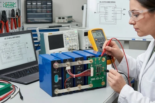
Before starting, make sure you have a compatible battery pack and BMS. A 4S LiFePO4 battery uses four individual 3.2V nominal cells connected in series. This configuration increases the total voltage while keeping the amp-hour capacity equal to that of one cell.
For example, four 3.2V, 100Ah LiFePO4 cells connected in series form a 12.8V, 100Ah battery pack, not a 400Ah battery pack.
You’ll need the following components:
-
Four compatible LiFePO4 cells with matching specifications.
-
A 4S LiFePO4 BMS.
-
Appropriately sized battery cables and connectors.
-
A digital multimeter for voltage measurements.
-
A compatible 4S LiFePO4 battery charger.
-
Insulation materials and suitable electrical protection.
Before choosing a BMS, check its continuous discharge current, maximum charging current, overcharge protection, overdischarge protection, and temperature monitoring features.
The BMS current rating should match the battery cells, wiring, connectors, and expected load. A 100A BMS, for example, does not automatically mean that your battery pack can safely deliver 100A.
Also, make sure the BMS is specifically designed for LiFePO4 chemistry. A BMS designed for conventional lithium-ion or LiPo batteries may use different voltage protection thresholds and should not be treated as interchangeable.
Part 2. Understand the 4S LiFePO4 BMS wiring terminals
Before connecting anything, identify the terminals on your BMS. Most conventional 4S BMS designs use five battery-side sensing points: B-, B1, B2, B3, and B+.
Each terminal corresponds to a particular position in the series-connected battery pack.
|
BMS terminal |
Connection point |
Function |
|---|---|---|
|
B- |
Cell 1 negative |
Total battery negative reference |
|
B1 |
Cell 1 positive |
Monitors Cell 1 |
|
B2 |
Cell 2 positive |
Monitors Cells 1 and 2 |
|
B3 |
Cell 3 positive |
Monitors Cells 1, 2, and 3 |
|
B+ |
Cell 4 positive |
Total battery positive |
|
P- |
Load and charger negative |
Common-port output |
|
C- |
Charger negative |
Separate charging port, if supported |
The B1, B2, and B3 terminals are connected to the junctions between successive cells. They allow the BMS to monitor individual cell voltages rather than relying only on the total battery voltage.
For example, the voltage between B- and B1 represents Cell 1 voltage. The voltage between B1 and B2 represents Cell 2 voltage.
One important detail: some manufacturers use B0, BC0, or other labels for the first sensing point. These names can refer to the same electrical reference as B-, but you should always confirm the specific terminal definitions in your BMS manual.
What about P- and C-?
These terminals depend on the BMS design:
-
Common-port BMS: Uses P- as the shared negative connection for charging and discharging.
-
Separate-port BMS: Uses C- for charging and P- for discharging.
Some models also use a common positive connection, while others have additional terminals or connectors. Never assume that every 4S BMS follows the same layout.
Part 3. Understand the 4S LiFePO4 BMS wiring diagram
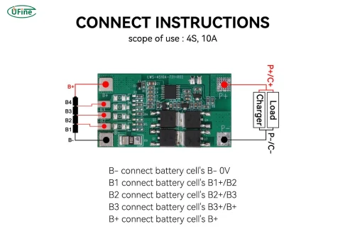
Before connecting the BMS, you need to understand how four battery cells are connected in series.
In a standard 4S configuration, the positive terminal of each cell connects to the negative terminal of the next cell. This creates three intermediate connection points and two main battery terminals.
The connection sequence looks like this:
Pack Negative                                      Pack Positive
    |                                                    |
  Cell 1          Cell 2          Cell 3          Cell 4
  (-) (+)---------(-) (+)---------(-) (+)---------(-) (+)
   |    |           |    |           |    |           |    |
  B-   B1          B1   B2          B2   B3          B3   B+
The diagram illustrates the electrical relationship between the four cells and the sensing points. Each shared connection between two cells is one balance measurement point.
For a standard 3.2V LiFePO4 cell, the expected pack voltage values are:
|
Measurement |
Nominal voltage |
Typical full-charge voltage |
|---|---|---|
|
Cell 1 |
3.2V |
3.65V |
|
Cell 2 |
3.2V |
3.65V |
|
Cell 3 |
3.2V |
3.65V |
|
Cell 4 |
3.2V |
3.65V |
|
4S battery pack |
12.8V |
14.6V |
These are reference values, not guaranteed measurements. Actual readings depend on the cells’ state of charge, temperature, and condition.
The BMS uses the individual voltage measurements to identify abnormal cell conditions and activate the appropriate protection functions.
Part 4. How to connect a 4S LiFePO4 BMS step by step
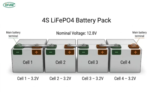
Now that you understand the terminal layout, let’s look at the actual connection process.
The most important thing is to connect the battery cells and sensing wires correctly. Do not rush this process. A reversed balance wire or incorrect connection can damage the BMS immediately.
1 Connect the four LiFePO4 cells in series
Start by connecting the four cells in the correct order:
-
Connect Cell 1 positive to Cell 2 negative.
-
Connect Cell 2 positive to Cell 3 negative.
-
Connect Cell 3 positive to Cell 4 negative.
After making these connections, Cell 1 negative becomes the total pack negative, while Cell 4 positive becomes the total pack positive.
Check that the cells have compatible voltage levels and that the pack polarity is correct before proceeding.
2 Identify the main battery terminals
Locate the two ends of the battery pack:
-
Pack negative: Cell 1 negative.
-
Pack positive: Cell 4 positive.
Use a multimeter to measure the total pack voltage. For four cells at approximately 3.2V each, you should see around 12.8V.
If the reading is significantly different from what you expect, stop and investigate the cell connections before installing the BMS.
3 Connect the BMS main negative wire
Locate the B- terminal or main negative wire on the BMS.
Connect it to the total negative terminal of the battery pack, which is the negative terminal of Cell 1.
This connection provides the BMS with its main battery-negative reference. Make sure the connection is secure and properly insulated.
4 Connect the balance wires in the correct order
This is one of the most important parts of the installation.
The balance wires need to connect to the corresponding battery junctions:
-
B- or B0: Total battery negative.
-
B1: Positive terminal of Cell 1.
-
B2: Positive terminal of Cell 2.
-
B3: Positive terminal of Cell 3.
-
B+: Positive terminal of Cell 4.
Some BMS models use a preassembled balance connector with five wires. Others have individual connection wires.
Regardless of the connector design, the electrical order must remain correct.
Do not assume that the physical wire order is identical across different BMS models. Follow the manufacturer’s wiring diagram and specified connection sequence. Some manufacturers require the balance harness to be connected to the battery first and plugged into the BMS only after voltage verification.
5 Connect the charger and load
Next, identify whether your BMS uses a common-port or separate-port configuration.
For a common-port design, the negative terminals of both the charger and load connect to P-. Their positive terminals connect to the battery positive side, provided the BMS manual specifies this arrangement.
For a separate-port design, the charger negative connects to C-, while the load negative connects to P-. Positive connections depend on the specific board design.
Use a charger designed for 4S LiFePO4 batteries, with a charging profile appropriate for the cells and battery manufacturer’s specifications.
Step 6: Inspect the wiring before operation
Before connecting a charger or powering a load, inspect the complete assembly.
Check that the balance wires are in the correct order, all positive and negative connections have the correct polarity, and no exposed conductors can touch each other.
Follow the manufacturer’s prescribed procedure for connecting the balance harness to the BMS. Never insert or remove a balance connector while the battery is energized unless the manufacturer explicitly permits it.
Part 5. How to check the 4S LiFePO4 BMS connections
Once the wiring is complete, use a digital multimeter to verify that the BMS is receiving the correct voltage information.
You should check both the individual cell voltages and the total battery pack voltage.
Start by measuring the voltage between adjacent sensing points. These readings represent the voltage of each individual cell.
For example:
-
B- to B1 measures Cell 1 voltage.
-
B1 to B2 measures Cell 2 voltage.
-
B2 to B3 measures Cell 3 voltage.
-
B3 to B+ measures Cell 4 voltage.
You can also measure cumulative voltage from B- to each successive sensing point to confirm that the readings increase in the expected order.
If one measurement is zero, negative, or significantly different from the corresponding cell voltage, do not connect the BMS until the problem has been identified.
Next, compare the sum of the four individual cell voltages with the total battery pack voltage.
The basic relationship is:
Vpack=V1+V2+V3+V4For example, if the four cells measure 3.25V, 3.24V, 3.26V, and 3.25V:
Vpack=3.25+3.24+3.26+3.25=13.00VThe total pack voltage should be approximately 13.00V.
After confirming the sensing connections, follow the BMS manufacturer’s procedure to check its output voltage and protection functions. Some BMS units may not activate their output until a compatible charger or activation procedure is applied.
For additional guidance, you can refer to the, which explains balance-wire identification and voltage detection.
Part 6. Common 4S LiFePO4 BMS wiring mistakes
Even when the wiring diagram looks simple, several mistakes can cause problems during installation.
Connecting balance wires in the wrong order
This is one of the most serious wiring mistakes. Each balance wire must correspond to the correct cell junction. Reversing the sequence can expose the BMS sensing circuit to an incorrect voltage and potentially damage the board.
Reversing battery polarity
Connecting B- to the positive terminal or B+ to the negative terminal can cause immediate electrical damage. Always verify polarity with a multimeter rather than relying only on cable colors.
Using the wrong type of BMS
A 4S LiFePO4 battery requires a BMS designed for LiFePO4 chemistry. A conventional 4S Li-ion or LiPo BMS generally uses different cell voltage thresholds.
For example, a standard 4S Li-ion or LiPo pack typically has a 16.8V full-charge voltage, while a 4S LiFePO4 pack typically charges to 14.6V.
Connecting the charger to the wrong terminal
A common-port BMS and a separate-port BMS may have different charging connections. Connecting the charger to the wrong terminal can prevent normal charging or cause electrical problems.
Choosing an undersized BMS
A BMS with insufficient continuous discharge or charging current may trigger protection during normal operation. Always consider the actual load requirements and the current limitations of the cells and wiring.
Ignoring temperature protection
LiFePO4 batteries have temperature limits for charging and discharging. In particular, charging below the cell manufacturer’s permitted minimum temperature can cause lithium plating and permanent battery damage. A suitable BMS should provide temperature monitoring and, where required, low-temperature charging protection.
FAQs
What voltage should a 4S LiFePO4 battery have?
A 4S LiFePO4 battery has a nominal voltage of 12.8V. Its typical full-charge voltage is 14.6V, based on 3.65V per cell. The actual operating voltage changes with the battery’s state of charge and load.
Can I use a 4S Li-ion BMS for a 4S LiFePO4 battery?
No, not unless the manufacturer explicitly specifies compatibility with both chemistries. Conventional lithium-ion and LiFePO4 batteries have different charging voltages and protection thresholds. Using an incompatible BMS can lead to improper protection.
Why is my 4S LiFePO4 BMS not charging the battery?
Several issues can prevent charging, including incorrect balance-wire connections, low-voltage protection, temperature protection, an incompatible charger, or a disconnected charging port. Check the BMS status indicators and manufacturer troubleshooting instructions before attempting to reset it.
Why does my 4S LiFePO4 BMS get warm during operation?
Some heat generation is normal because MOSFETs and other electronic components have electrical resistance. Excessive heating may indicate high current, undersized wiring, poor connections, or a BMS operating beyond its rated limits. Check the manufacturer’s temperature specifications and investigate unusual heating immediately.
What is the difference between a 4S BMS with Bluetooth and a standard BMS?
A Bluetooth-enabled BMS can communicate battery information to a smartphone or other compatible device. Depending on the model, you may be able to monitor individual cell voltages, pack current, temperature, state of charge, and protection events. A standard BMS may provide protection without wireless monitoring.
Related Tags:

More Articles

What Happens If One Cell in a Battery Pack Goes Bad? How to Fix It
Found a faulty battery cell? Discover how to identify the problem, whether one cell can be replaced, and how to fix a battery pack safely.
Learn 24V Battery Management System
Need a 24V battery management system? Explore wiring diagrams, BMS current ratings, charging compatibility, battery protection, and troubleshooting tips.
How a Series BMS Manages and Protects Lithium Battery Cells
Learn how Series BMS works in lithium battery packs, including cell balancing methods, wiring connections, protection features, and common mistakes.
20S BMS Wiring Diagram: A Step-by-Step Connection Guide
Building a 20S battery pack? Discover how to connect BMS terminals, check balance wires, calculate discharge current, and choose the right protection system.
Can Power Bank Charge an Action Camera Battery?
Find out which power banks work with action cameras, whether you can record while charging, and what to use when your camera runs out of power.