- Part 1. What is a 20S battery pack?
- Part 2. What is a BMS and why does a 20S battery pack need one?
- Part 3. 20S BMS wiring diagram and connection layout
- Part 4. How to connect a BMS to a 20S battery pack step by step
- Part 5. How to calculate the required BMS current for a 20S battery pack
- Part 6. How to choose the right BMS for a 20S battery pack
- Part 7. Common 20S BMS wiring problems and troubleshooting
- Part 8. Frequently asked questions about 20S BMS wiring
If you are building a 20S lithium battery pack, understanding the correct BMS wiring configuration is particularly important. With 20 cells connected in series, even a small wiring mistake can lead to incorrect voltage readings, protection failures, or potential battery damage.
This guide explains the 20S BMS wiring diagram, how to connect the balance wires and main terminals, how to calculate the required BMS current, and how to choose a compatible BMS for your battery pack.
Key takeaways
-
A 20S battery pack contains 20 cells connected in series, with 21 voltage monitoring points for a conventional balance-wire BMS.
-
A 20S lithium-ion or standard 3.7V LiPo battery pack typically has a nominal voltage of 74V and a full-charge voltage of 84V.
-
BMS wiring terminals commonly include B-, B+, P-, C-, and balance connections, although terminal layouts vary by manufacturer.
-
The required BMS current depends on the load power, minimum operating voltage, and system efficiency.
-
Always match the BMS to the battery chemistry, cell voltage limits, current requirements, and protection specifications.
Part 1. What is a 20S battery pack?
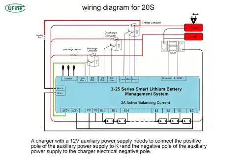
1.1 What does 20S mean in battery configuration?
The letter S stands for series. A 20S battery pack consists of 20 individual battery cells connected in series, with the positive terminal of one cell connected to the negative terminal of the next.
Connecting cells in series increases the total voltage, while the capacity in amp-hours (Ah) remains the same.
For example, if you connect twenty 3.7V lithium polymer cells, the resulting battery pack has a nominal voltage of 74V.
If each cell has a capacity of 5Ah, the 20S pack will also have a capacity of 5Ah, assuming a 20S1P configuration.
1.2 20S lithium battery voltage chart
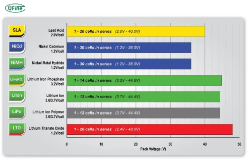
The voltage of a 20S battery pack depends on its cell chemistry. Before selecting a BMS, you need to understand the nominal voltage, full-charge voltage, and discharge cutoff voltage of your cells.
For a conventional 3.7V lithium-ion or LiPo battery cell, the typical voltage values are:
|
Voltage specification |
Single cell |
20S battery pack |
|---|---|---|
|
Nominal voltage |
3.7V |
74V |
|
Full charge voltage |
4.2V |
84V |
|
Approx. cutoff at 3.0V/cell |
3.0V |
60V |
|
Lower cutoff at 2.5V/cell |
2.5V |
50V |
These cutoff values are examples, not universal operating limits. The actual discharge limit must follow the cell manufacturer’s datasheet and the BMS protection settings.
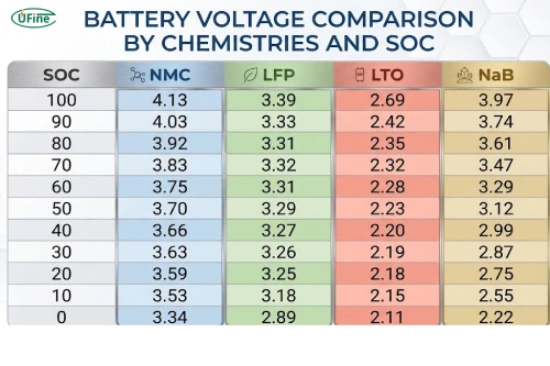
For comparison, a 20S LiFePO4 battery pack has a different voltage profile:
|
Voltage specification |
Single cell |
20S battery pack |
|---|---|---|
|
Nominal voltage |
3.2V |
64V |
|
Full charge voltage |
3.65V |
73V |
|
Typical lower voltage reference |
2.5V |
50V |
This is why you should never choose a BMS based on the 20S configuration alone. Battery chemistry matters just as much.
Part 2. What is a BMS and why does a 20S battery pack need one?
A Battery Management System (BMS) is an electronic control system that monitors and manages a rechargeable battery pack. In a 20S configuration, it monitors the voltage of individual cells or cell groups rather than simply measuring the total pack voltage.
Without a properly configured BMS, individual cells may become overcharged, excessively discharged, or overloaded even when the total pack voltage appears normal.
2.1 Main functions of a 20S BMS
A typical 20S BMS provides several important protection and monitoring functions:
-
Overcharge protection: Stops charging when a cell reaches its maximum permitted voltage.
-
Overdischarge protection: Disconnects the load when a cell falls below its permitted discharge voltage.
-
Overcurrent protection: Protects the battery from excessive charging or discharging current.
-
Short circuit protection: Disconnects the output when a short circuit is detected.
-
Cell balancing: Helps maintain similar voltage levels across individual cells.
-
Temperature protection: Monitors battery or MOSFET temperature and responds to abnormal conditions.
The exact protection functions depend on the BMS design and configuration. For example, some models include temperature sensors and communication interfaces, while simpler models provide basic voltage and current protection.
2.2 Why cell balancing matters
In a 20S battery pack, individual cells do not always maintain exactly the same voltage during charging and discharging.
Over time, small differences in cell capacity, internal resistance, and self-discharge can cause voltage imbalance.
A balancing function helps reduce these differences by managing the voltage of individual cells. Passive balancing typically dissipates excess energy as heat, while active balancing transfers energy between cells.
For a high-voltage battery pack, balancing is particularly useful because one cell reaching its voltage limit can trigger the BMS and interrupt the operation of the entire pack.
Part 3. 20S BMS wiring diagram and connection layout
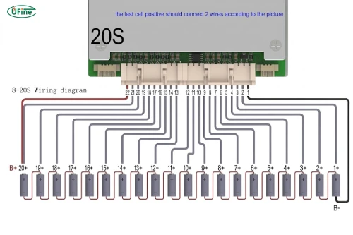
Before connecting a BMS, you need to understand its terminal labels. Although the exact layout varies between manufacturers, most conventional 20S BMS designs have main power terminals and individual cell voltage monitoring connections.
3.1 Understanding the main BMS terminals
The following are common terminal labels:
|
Terminal |
Function |
|---|---|
|
B- |
Battery pack negative connection |
|
B+ |
Battery pack positive connection |
|
P- |
Discharge/load negative connection |
|
C- |
Charging negative connection on separate-port BMS |
|
B0–B20 |
Individual cell voltage monitoring connections |
On a common-port BMS, charging and discharging share the same negative output terminal, usually P-.
On a separate-port BMS, charging and discharging use different negative terminals, usually C- and P-.
Some BMS models use different labels or terminal arrangements. Always check the manufacturer’s wiring diagram before making connections.
3.2 20S BMS wiring diagram
A conventional 20S battery pack requires 21 voltage monitoring points: one at the battery negative end and one at each successive series connection, ending at the positive end.
The simplified configuration looks like this:
20S Battery Pack

Pack Negative                         Pack Positive
     |                                      |
    B0                                     B20
     |                                      |
     +-- Cell 1 -- Cell 2 -- ... -- Cell 20+
          |         |                  |
         B1        B2                 B20

BMS Balance Connections:
B0, B1, B2, B3 ... B19, B20

BMS Main Connections:
B-  -> Battery Pack Negative
B+  -> Battery Pack Positive
P-  -> Load Negative
C-  -> Charger Negative (separate-port BMS)
This is a conceptual illustration, not a universal wiring instruction. The actual balance harness and connection sequence must follow the exact BMS manufacturer’s diagram.
3.3 Common-port vs. separate-port BMS wiring
The main difference between these two designs is how they handle charging and discharging.
Common-port BMS
A common-port BMS uses one negative terminal for both charging and discharging. The charger and load share the P- connection.
Separate-port BMS
A separate-port BMS provides independent charging and discharging negative terminals. The charger connects to C-, while the load connects to P-.
Neither design is automatically better for every application. Your choice depends on the charging system, load requirements, and the battery management functions you need.
Part 4. How to connect a BMS to a 20S battery pack step by step
Connecting a BMS requires careful attention to voltage polarity and balance wire order. A wiring mistake can damage the BMS or create a dangerous electrical fault.
For a 20S high-voltage pack, this work should be performed by a qualified battery technician using the manufacturer’s documented procedure.
1 Prepare the battery cells and BMS
First, confirm that all 20 cells are compatible with each other in chemistry, capacity, and operating specifications.
Check the BMS documentation to verify that it supports:
-
20 cells connected in series.
-
The correct lithium battery chemistry.
-
The required charging and discharging current.
-
The appropriate cell voltage protection limits.
-
The correct balance wire configuration.
Also inspect the wiring harness, insulation, connectors, and temperature sensors before installation.
2 Connect the main battery terminals
Identify the battery pack’s positive and negative terminals and compare them with the BMS terminal markings.
The main battery connections typically include B- and B+, while the output and charging connections depend on whether the BMS uses a common-port or separate-port design.
Do not assume that the physical position of a terminal indicates its function. Follow the manufacturer’s specified connection sequence and voltage-check procedure.
3 Connect the balance wires
The balance harness monitors the voltage at each successive series connection.
For a conventional 20S BMS, the harness has 21 sensing connections, corresponding to B0 through B20.
Each sensing point must connect to its designated battery node. The voltage between adjacent sensing points represents the voltage of one cell.
Before inserting the balance connector, verify the voltage at every adjacent pin pair and compare the readings with the BMS documentation.
Important: Never connect the balance harness by guessing the wire order. Incorrect connections can expose BMS input circuits to excessive voltage and permanently damage the board.
4 Connect the charging and discharging terminals
After the main and balance connections have been verified, connect the charger and load according to the BMS port configuration.
For a common-port design, both charger and load generally share P-.
For a separate-port design, the charger uses C- and the load uses P-.
The charger must also match the battery pack’s chemistry and charging voltage. For a conventional 20S 3.7V LiPo pack, this typically means an 84V maximum charging voltage, provided the cells are rated for 4.2V maximum per cell.
5 Inspect and verify all connections
Before powering the system, check the wiring against the manufacturer’s diagram.
Verify that:
-
The main positive and negative connections have the correct polarity.
-
All 20 cell voltages are within their specified operating ranges.
-
The 21 balance sensing points are in the correct order.
-
No exposed conductors can cause a short circuit.
-
Temperature sensors and communication connections are correctly installed.
A qualified technician should then verify BMS readings and protection functions using the manufacturer’s commissioning procedure before the battery pack is put into service.
Part 5. How to calculate the required BMS current for a 20S battery pack
Choosing the correct BMS current rating is just as important as selecting the right voltage rating.
A BMS with insufficient current capacity may repeatedly trigger overcurrent protection, overheat, or limit the performance of the connected device.
5.1 Calculate the required continuous discharge current
You can estimate the battery current using the following formula:
Current (A) = Power (W) / Voltage (V)For a more practical system calculation that accounts for conversion losses:
Required Current (A) =
Load Power (W) / (Minimum Battery Voltage (V) × Efficiency)
For example, suppose your 20S battery pack powers a 1,000W device.
Assume:
-
Load power: 1,000W
-
Minimum operating battery voltage: 60V
-
System efficiency: 90% (0.90)
The calculation is:
Required Current = 1000 / (60 × 0.90)

Required Current = 18.52A
This means the battery may need to deliver approximately 18.52A under the specified operating conditions.
A BMS rated for 20A continuous discharge would leave very little operating margin. You should evaluate a higher-rated model based on thermal conditions, actual load profiles, and the manufacturer’s derating specifications.
5.2 Consider peak discharge current
Some electronic devices draw significantly more current during startup than during normal operation.
For example, motors, compressors, and other inductive loads can produce temporary current spikes.
Therefore, you should consider both continuous and peak discharge current when choosing a BMS.
A BMS rated for 30A continuous current with a suitable peak-current capability may be more appropriate than a lower-rated model, depending on the actual application.
However, the peak rating must include its permitted duration. A 60A peak rating for one second is not equivalent to a 60A continuous rating.
5.3 Check the charging current requirement
The charging current rating also matters.
If your charger supplies 5A, the BMS must support at least that charging current under the intended operating conditions.
You should also check the battery cells’ maximum permitted charging current. A BMS with a 20A charging rating does not mean the cells themselves can safely accept 20A.
The final charging current must stay within the limits of both the battery cells and the BMS.
Part 6. How to choose the right BMS for a 20S battery pack
Choosing a BMS involves more than matching the number of cells in series. You also need to consider the battery chemistry, electrical load, charging requirements, and operating environment.
6.1 Match the BMS to battery chemistry
Different lithium battery chemistries have different voltage limits.
For example, a standard 3.7V LiPo battery cell typically reaches 4.2V when fully charged, while a LiFePO4 cell typically reaches 3.65V.
Therefore, a 20S LiPo battery pack requires a different voltage configuration from a 20S LiFePO4 battery pack.
Using an incompatible BMS can result in incorrect protection thresholds and unsafe charging conditions.
6.2 Select the appropriate current rating
The BMS continuous discharge rating should meet the maximum expected operating current, with sufficient margin for temperature, enclosure conditions, and component limitations.
You should also check the peak discharge rating, charging current rating, and MOSFET thermal performance.
6.3 Consider additional BMS features
Depending on your application, you may need additional functions such as:
- Bluetooth monitoring for battery status.
- CAN or UART communication with the main controller.
- External temperature sensors.
- Active cell balancing.
- Configurable overvoltage and undervoltage thresholds.
For consumer electronics and customized battery packs, these features can help improve system monitoring and simplify product integration.
Part 7. Common 20S BMS wiring problems and troubleshooting
Even when the battery pack is correctly assembled, incorrect BMS configuration or wiring can cause operational problems.
Here are several common situations you may encounter.
BMS does not power on
If the BMS does not start, check the main battery connections, polarity, and individual cell sensing voltages.
Some BMS models also require an activation signal or charger connection before their output becomes available.
Battery pack cannot charge
Charging problems may occur when the BMS detects overvoltage, undervoltage, excessive temperature, or an abnormal charging current.
Check the individual cell voltage readings and confirm that the charger voltage matches the battery chemistry and series configuration.
Battery pack cannot discharge
If the battery pack cannot supply power, the BMS may have activated overcurrent, short circuit, or undervoltage protection.
Inspect the load connections and review the BMS fault status before attempting to reset the system.
Incorrect cell voltage readings
Incorrect voltage readings may indicate reversed balance connections, loose connectors, damaged sensing wires, or incorrect BMS configuration.
Do not continue operating the battery pack until the sensing connections have been checked and the readings are consistent with independent measurements.
Part 8. Frequently asked questions about 20S BMS wiring
How many balance wires does a 20S BMS have?
A conventional 20S BMS uses 21 voltage sensing connections, including the battery pack negative reference and the 20 successive series connection points. The physical harness design may vary between manufacturers.
What is the full charge voltage of a 20S lithium battery pack?
For a standard 3.7V lithium-ion or LiPo battery with a maximum charging voltage of 4.2V per cell, a 20S battery pack has a full charge voltage of 84V.
Can I use a 20S BMS with a 20S LiPo battery?
Yes, provided the BMS explicitly supports the LiPo cell chemistry and its voltage limits. You should also verify its continuous current, charging current, balancing, and temperature protection specifications.
What happens if BMS balance wires are connected incorrectly?
Incorrect balance wire connections can cause inaccurate cell voltage readings, BMS malfunction, damaged sensing circuits, or short circuits. Always follow the manufacturer’s wiring diagram and verify every connection before inserting the balance connector.
Does a 20S BMS increase battery capacity?
No. A BMS does not increase the battery pack’s capacity. Its primary purpose is to monitor and protect the battery cells. The total capacity depends on the capacity and parallel configuration of the cells.
Related Tags:

More Articles

Can Power Bank Charge an Action Camera Battery?
Find out which power banks work with action cameras, whether you can record while charging, and what to use when your camera runs out of power.
Compare DJI Osmo batteries by model, capacity, runtime, and compatibility. Find the right battery before you buy and avoid costly mistakes.
Are GoPro Batteries Interchangeable? A Model-by-Model Guide
Compare GoPro batteries by model, price, capacity, and runtime. Find compatible options, avoid costly mistakes, and choose the best battery for you.
How to Reduce Power Consumption and Extend Battery Life
Discover practical ways to reduce power consumption, eliminate hidden energy waste, and extend battery life in portable electronic devices
Power Consumption Calculator: Calculate Watts & Battery Life
Find out how much power your electronic device consumes. Learn easy calculations, understand battery energy, and estimate runtime before choosing a battery.